Refrigerated liquid dispensing system

a liquid dispensing system and refrigerated technology, applied in the direction of liquid transferring devices, domestic cooling devices, lighting and heating devices, etc., can solve the problems of dangerously high bacteria level, need to replace empty bottles, and water coolers as conventionally used create serious health hazards, etc., to achieve the effect of avoiding the use of disposable containers or bottles

Inactive Publication Date: 2006-07-18
MULLEN JAMES T
View PDF11 Cites 42 Cited by
  • Summary
  • Abstract
  • Description
  • Claims
  • Application Information

AI Technical Summary

Benefits of technology

[0003]An object of this invention is to provide a refrigerated liquid dispenser system which can readily use disposable containers or bottles thereby eliminating the need to continually cleanse, sanitize and fill each container or bottle for future use.
[0004]Another object of this invention is to provide a refrigerated liquid dispensing system whereby each time a user replaces a container or bottle the total dispensing system is replaced. This removes the need to clean and sanitize the system as well as the need to return empty containers or bottles. Thus, the coordination of the system evolves from a two-way delivery structure generally used in the prior art to a one-way delivery system of this invention.
[0012]A distinct advantage with the various practices of this invention is to minimize the likelihood of bacteria in the system, particularly in the valve portion of the system. In that regard, the valve is permanently connected to the container and thus the valve is disposed of along with the container. Further, in the practice of the invention where the liquid is dispensed by having a refrigerated compartment with the door closed the only portion of the valve not contained within the refrigerated compartment is the small tip of the valve stem. In the embodiment of the invention where the liquid is dispensed while the door is opened all of the valve components are maintained within the refrigerated compartment during non-use. This feature of having all or substantially all of the valve components within the refrigerated compartment during periods of non-use further minimizes the possibility of bacteria contaminating the system.

Problems solved by technology

Such water coolers as conventionally used create serious health dangers because of the lack of proper sanitation.
For example, the bacteria level could be dangerously high.
A further complaint of customers of bottled water systems is the need to replace the empty bottle with a filled bottle which could weigh, for example, 43 pounds.

Method used


Image

  • Refrigerated liquid dispensing system
  • Refrigerated liquid dispensing system
  • Refrigerated liquid dispensing system

Examples


Embodiment Construction

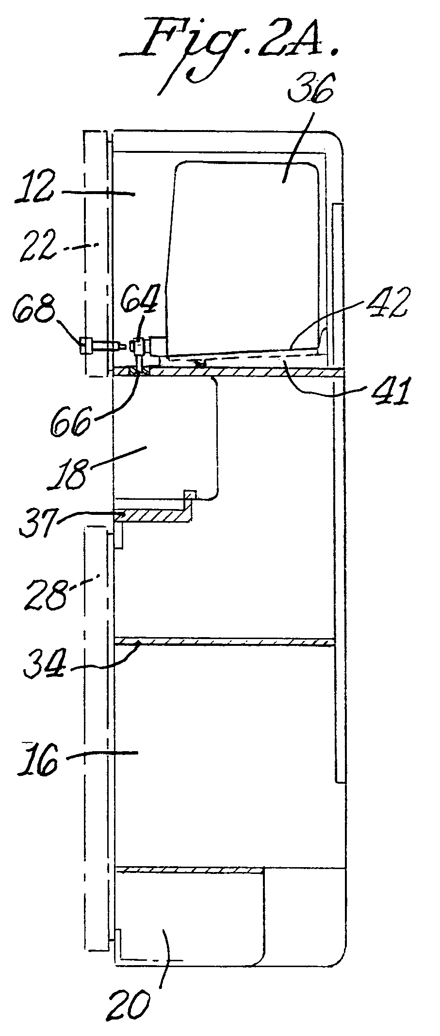
[0026]FIGS. 1–4 illustrate a refrigerated liquid dispensing system 10 in accordance with one embodiment of this invention. As shown therein, system 10 includes a cabinet 12 which is divided into a plurality of different sections. One of the sections includes an upper or top refrigerated compartment 14, a bottom or lower refrigerated compartment 16, and an intermediate cup holder area 18 which is recessed into the cabinet. A compressor section 20 is provided at the bottom of the cabinet to cool the top compartment 14 and bottom compartment 16 in a conventional manner which could include, for example, an evaporator extending between the two refrigerated compartments at the rear side of the cabinet. The back wall of the cabinet could contain a screen type plate having vent holes for the escape of heat and outward projections to assure that the cabinet would be spaced from the wall of a room.

[0027]A door 22 is located in the vertical front wall of cabinet 12 to selectively open and clos...


PUM


Abstract

A refrigerated liquid dispensing system includes a cabinet having a refrigerated compartment. At least one liquid container such as a water bottle is mounted in a receptacle in the compartment. A valve is mounted to the neck of the bottle for controlling the flow of liquid from the bottle. In one practice of the invention the valve is actuated by a spring plunger mounted to the door of the compartment so that the valve can be actuated without opening the door to dispense water from a valve stem into a cup in a cup holder area below the compartment. In a further practice of the invention the valve is actuated by opening the door and acting directly on the valve. When the door opens a valve extension automatically slides outwardly so that a dispensing opening in the valve extension is disposed against a cup in the cup holder area.

Description

BACKGROUND OF THE INVENTION[0001]Liquid dispensers are used wherein a container, such as a bottle, is associated with a cooling or refrigeration system so that the water or other liquid, such as milk, cream, juices, ice tea, fruit drinks, lemonade, wine and other liquids will be cool. Such use of liquid dispensers has been common in restaurants, bars, cafeterias, convenience stores, offices, homes and factories. It is a common practice where the water, for example, is then periodically dispensed into a cup or other receptacle. Such water coolers as conventionally used create serious health dangers because of the lack of proper sanitation. For example, the bacteria level could be dangerously high. The worst offenders are coolers with quick bottle-replacement rate.[0002]A further complaint of customers of bottled water systems is the need to replace the empty bottle with a filled bottle which could weigh, for example, 43 pounds. The bottled water industry is growing rapidly, with cust...

Claims


Application Information

Patent Timeline
Patent Type & Authority Patents(United States)
IPC IPC(8): B67D5/62B67D7/80
CPCB67D3/0009B67D1/0891F25D23/126
Inventor MULLEN, JAMES T.
Owner MULLEN JAMES T
Why Eureka
Try Eureka