Brake control for vehicle

a technology for brakes and vehicles, applied in brake systems, braking components, transportation and packaging, etc., can solve the problems of contradictory cancellation of regenerative braking and increase and achieve the effect of improving energy recovery efficiency and increasing the locking tendency of motor-driven wheels

Inactive Publication Date: 2006-07-18
NISSAN MOTOR CO LTD
View PDF26 Cites 24 Cited by
  • Summary
  • Abstract
  • Description
  • Claims
  • Application Information

AI Technical Summary

Benefits of technology

[0003]The application of the regenerative braking force beyond the allotment of the ideal distribution tends to increase the locking tendency of the motor-driven wheels, and to trigger the anti-skid brake control operation with the result of cancellation of the regenerative braking. In this case, however, the cancellat...

Problems solved by technology

The application of the regenerative braking force beyond the allotment of the ideal distribution tends to increase the locking tendency of the motor-driven wheels, and to trigger the anti-skid brake control operati...

Method used


Image

  • Brake control for vehicle
  • Brake control for vehicle
  • Brake control for vehicle

Examples


first embodiment

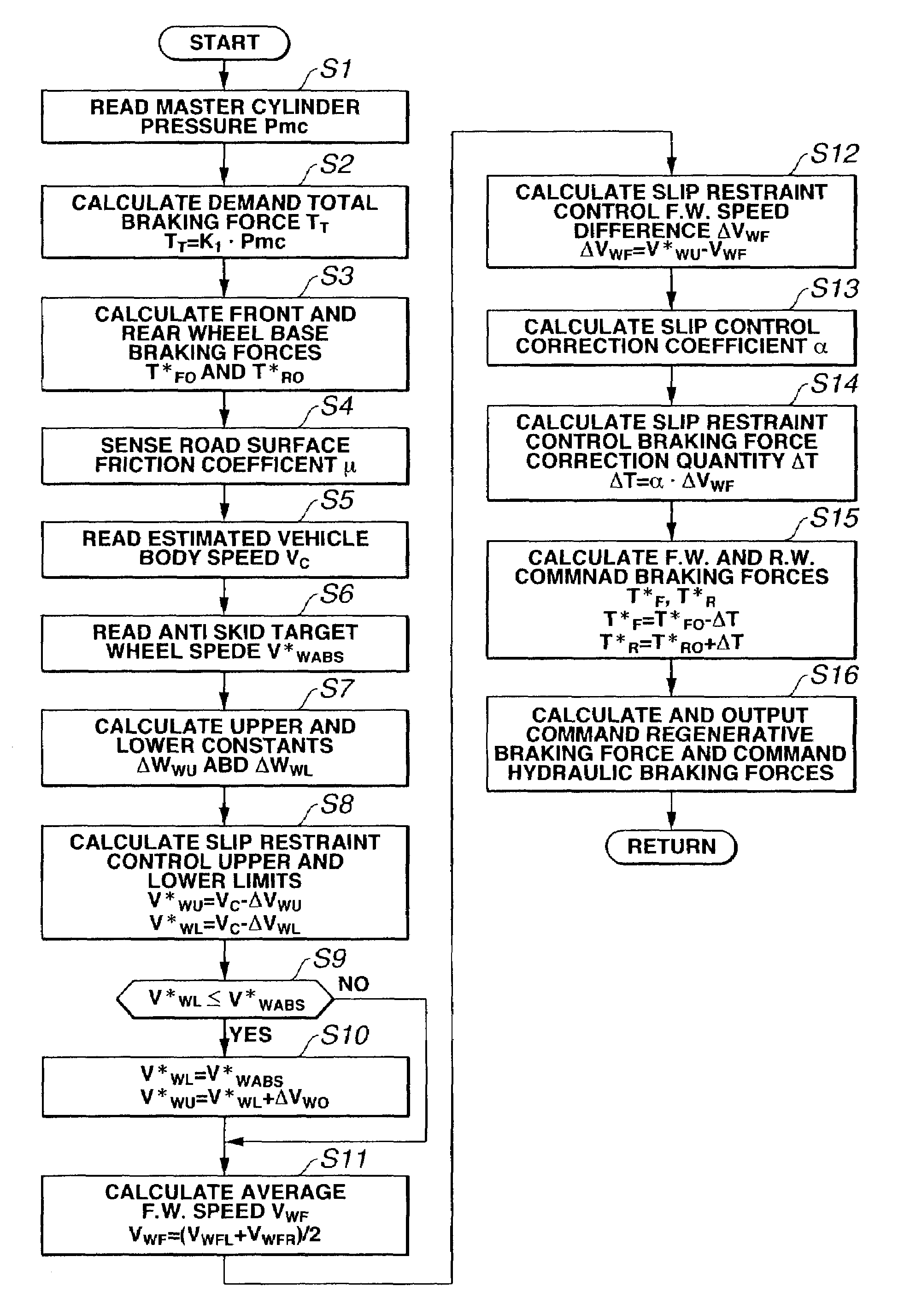
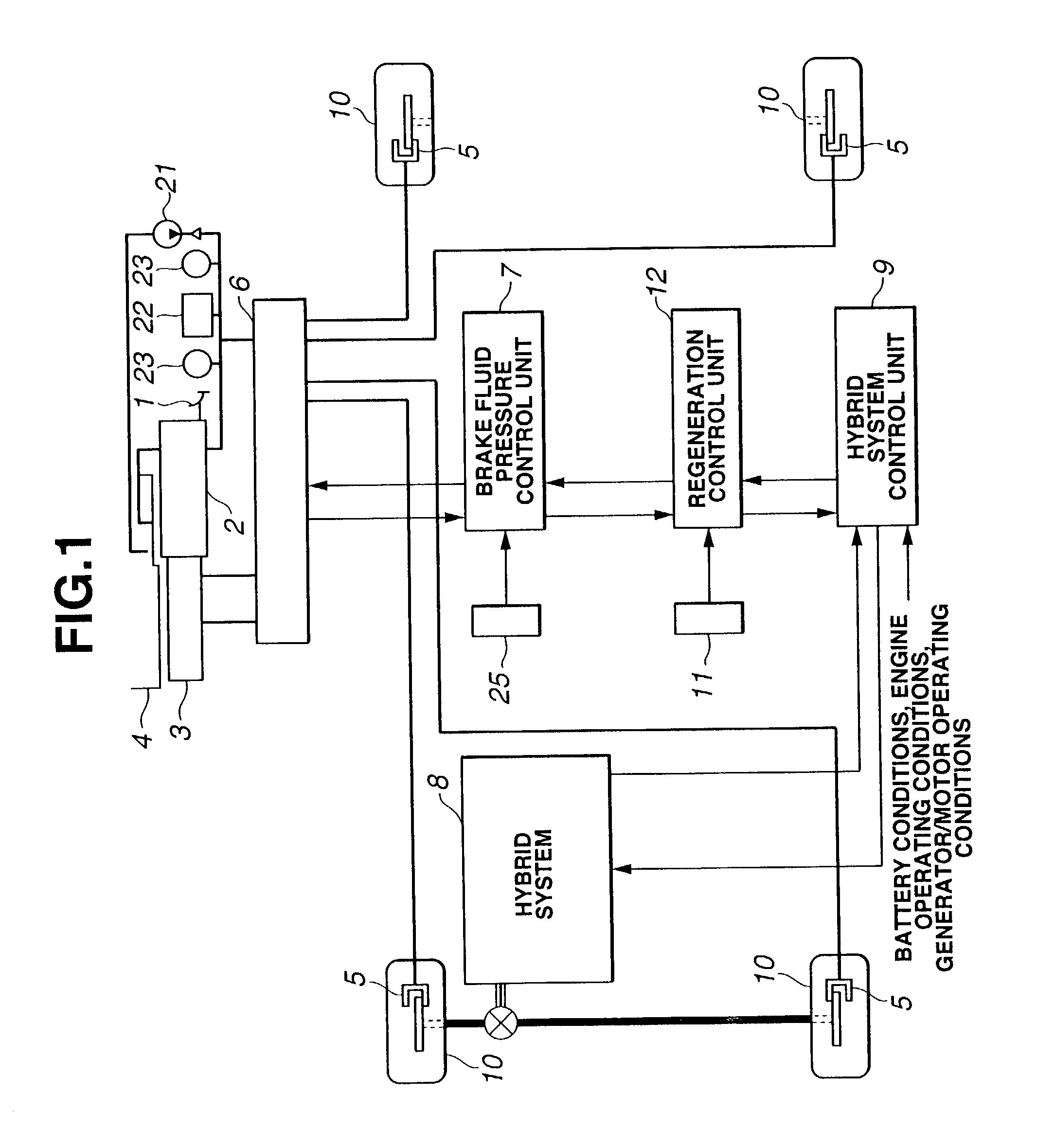
[0020]FIG. 1 shows a vehicle equipped with a brake control apparatus according to the present invention. In this embodiment, the present invention is applied to a cooperative regeneration brake control system arranged to control a brake fluid pressure in a pressure decrease mode during control of a regenerative brake torque by an ac synchronous motor, and thereby to recover regenerative energy efficiently.

[0021]A brake pedal 1 to be operated by the driver is connected through a booster 2 with a master cylinder 3. Booster 2 utilizes a high pressure brake fluid pressurized by a pump 21 and stored in an accumulator 22, to increase the effectiveness of pedal force, and supplies the increased force to master cylinder 3. Pressure switches 23 are used for controlling pump 21 in sequential control. There is further provided a reservoir 4 for storing the brake fluid.

[0022]A brake fluid pressure circuit 6 is interposed between master cylinder 3 and wheel cylinders 5 of wheels 10 of the vehicl...

second embodiment

[0066]Thus, the control system calculates slip restraint control reference speed VTHRC in accordance with estimated vehicle body speed Vc, and determines slip restraint control reference lower and upper limits VRMDRCINX and VRMDRCOUTX by subtracting quantity KVTHIN or KVTHOUT from the reference speed VTHRC. Therefore, it is possible to tune the slip restraint control reference lower and upper limits VRMDRCINX and VRMDRCOUTX readily to various vehicles merely by modifying Table 1 and equations used for the calculation. By contrast, in the method of setting slip restraint control reference lower and upper limits VRMDRCINX and VRMDRCOUTX by subtracting constant KVTHIN or KVTHOUT from estimated vehicle body speed Vc, the control system requires a table and equations for calculating each of VRMDRCINX and VRMDRCOUTX, the system becomes complex, and the tuning becomes troublesome.

[0067]Then, at step S304, regeneration control unit 12 examines whether slip restraint control reference lower...


PUM


Abstract

A brake control apparatus for a vehicle includes an actuating section to apply a regenerative braking force to a motor-driven wheel driven by a motor of the vehicle. A control section is arranged to vary the regenerative braking force in a direction to shift a front and rear wheel braking force distribution toward an ideal braking force distribution, in accordance with a wheel locking tendency of the motor-driven wheel when the regenerative braking force exceeding a braking force determined by the ideal braking force distribution is applied to the motor-driven wheel.

Description

BACKGROUND OF THE INVENTION[0001]The present invention relates to brake control apparatus and / or process for a vehicle having at least one wheel powered by an electric motor, and more specifically to brake control technique for controlling a braking force distribution between front and rear axles of a vehicle.[0002]To improve energy recovery efficiency, a brake control system of one example is arranged to apply, to drive wheels powered by a motor, a regenerative braking force exceeding a braking force corresponding to an ideal braking force distribution. In the case of a vehicle equipped with an anti-skid brake control (wheel slip brake control) function, a brake control system of one approach cancels a regenerative braking to drive wheels powered by a motor when an anti-skid brake control operation is started.SUMMARY OF THE INVENTION[0003]The application of the regenerative braking force beyond the allotment of the ideal distribution tends to increase the locking tendency of the mo...

Claims


Application Information

Patent Timeline
IPC IPC(8): B60T8/64B60L7/24B60T8/00B60T8/17B60T8/176B60T8/1761B60T8/1766B60T8/26B60T8/58B60T13/66B60W10/08B60W10/18B60W20/00
CPCB60T8/00B60T8/1766B60T13/662B60T8/267B60T2270/608
Inventor SASAKI, HIROKINAKAMURA, HIDEOTSUTSUMI, JUNJITAZOE, KAZUHIKOSUZUKI, HIDETOSHI
Owner NISSAN MOTOR CO LTD
Why Eureka
Try Eureka