Slewing type working machine

a working machine and slewing body technology, applied in the direction of fluid couplings, servomotors, couplings, etc., can solve the problem of preventing the hydraulic motor and the upper slewing body connected thereto from rotating, and achieve the effect of improving energy recovery efficiency

Inactive Publication Date: 2014-01-09
KOBELCO CONSTR MASCH CO LTD
View PDF7 Cites 20 Cited by
  • Summary
  • Abstract
  • Description
  • Claims
  • Application Information

AI Technical Summary

Benefits of technology

[0014]An object of the present invention is to provide a slewing-type working machine which is capable of improving energy recovery efficiency by reducing motor load at least during slewing deceleration, by use of a hydraulic-pilot-controlled selector valve and a communication selector valve for switching supply of pilot pressure to the hydraulic-pilot-controlled selector valve and which is capable of holding an upper slewing body in a stopped state even when a failure attributable to fixation of a spool or the like of the communication selector valve occurs. The slewing-type working machine provided by the present invention includes: a base carrier; an upper slewing body mounted on the base carrier so as to be capable of being slewed; a hydraulic motor which includes first and second ports and which receives supply of hydraulic fluid through one of the first and second ports and discharges the hydraulic fluid through the other port to thereby operate so as to drive the upper slewing body to slew it; a hydraulic pump which discharges the hydraulic fluid to be supplied to the hydraulic motor; a first pipe-line connecting the first port of the hydraulic motor to the control valve; a second pipe-line connecting the second port of the hydraulic motor to the control valve; a slewing operation device including an operating member to which an operation is applied to input a command for the driving to slew and being adapted to output an operation signal corresponding to the operation applied to the operating member; a control valve adapted to be operated, based on the operation signal from the slewing operation device, to control supply of hydraulic fluid to the hydraulic motor and control discharge of hydraulic fluid from the hydraulic motor and adapted to be held at a neutral position for cutting off both the first and second pipe-lines from the hydraulic pump and the tank when the operation signal is absent; a communication valve which comprises a hydraulic-pilot-controlled selector valve having a pilot port, the communication valve being adapted to be switched to a communication position for bringing a pipe-line corresponding to an outlet-side pipe-line that is the pipe-line on an outlet-side of the hydraulic motor of the first and second pipe-lines into direct communication with the tank while bypassing the control valve or communication with an inlet-side pipe-line that is the pipe-line on an inlet-side of the motor of the first and second pipe-lines when pilot pressure is supplied to the pilot port, while the communication valve being held at a communication cutoff position for cutting off the communication when the pilot pressure is not supplied to the pilot port; a hydraulic pilot pressure source which generates pilot pressure to be supplied to the communication valve; a communication selector valve which is provided on a pilot line for supplying pilot pressure from the hydraulic pilot pressure source to the pilot port of the communication valve and which is switched between a supply position for allowing the pilot pressure to be supplied to the communication valve and a position for cutting off the supply of the pilot pressure; a switching control valve which is provided on an inlet side of the communication selector valve and which is switched between a connecting position for connecting the hydraulic pilot pressure source to the communication selector valve and a cutoff position for cutting off the connection; and a controller which issues commands to the communication selector valve and the switching control valve for switching respective position of the communication selector valve and the switching control valve, wherein: at least during slewing deceleration, the controller issues a command to switch the switching control valve to the connecting position and a command to switch the communication selector valve to the supply position, thereby permitting the pilot pressure to be supplied to the pilot port of the communication valve to set the communication valve to the communication position; and, in a state where the slewing is stopped, the controller issues a command to switch the communication selector valve to the cutoff position and issues a command to switch the switching control valve to the cutoff position so as to bring the communication valve into the communication cutoff position regardless of an actual position of the communication selector valve.

Problems solved by technology

Hence, for example, in the case where the direct-interconnection selector valve is made up of the hydraulic-pilot-controlled selector valve, the direct-interconnection selector valve is brought into a state of directly interconnecting both of the pipe-lines, which makes it impossible to prevent the hydraulic motor and the upper slewing body connected thereto from rotation.

Method used


Image

  • Slewing type working machine
  • Slewing type working machine
  • Slewing type working machine

Examples


first embodiment

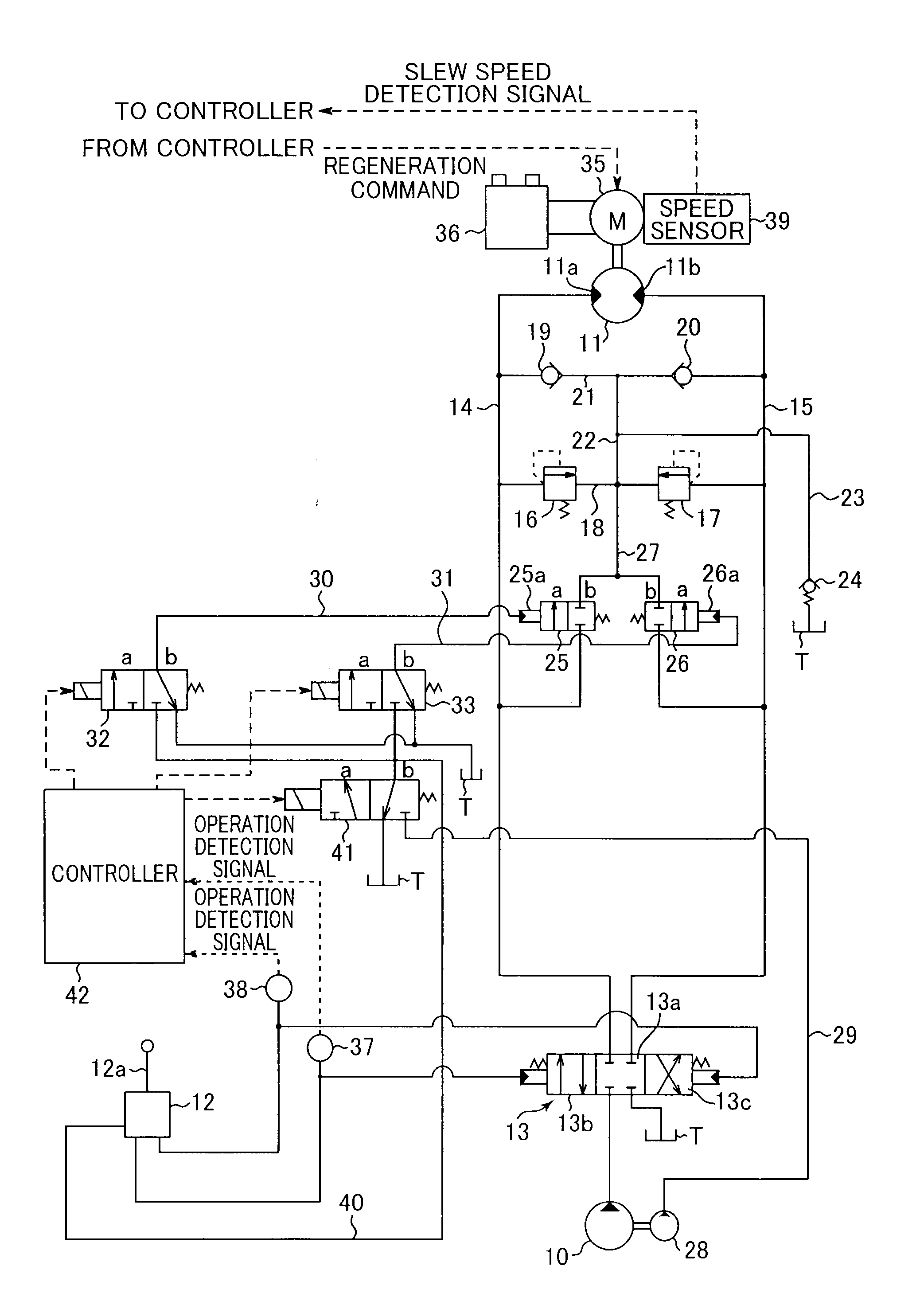
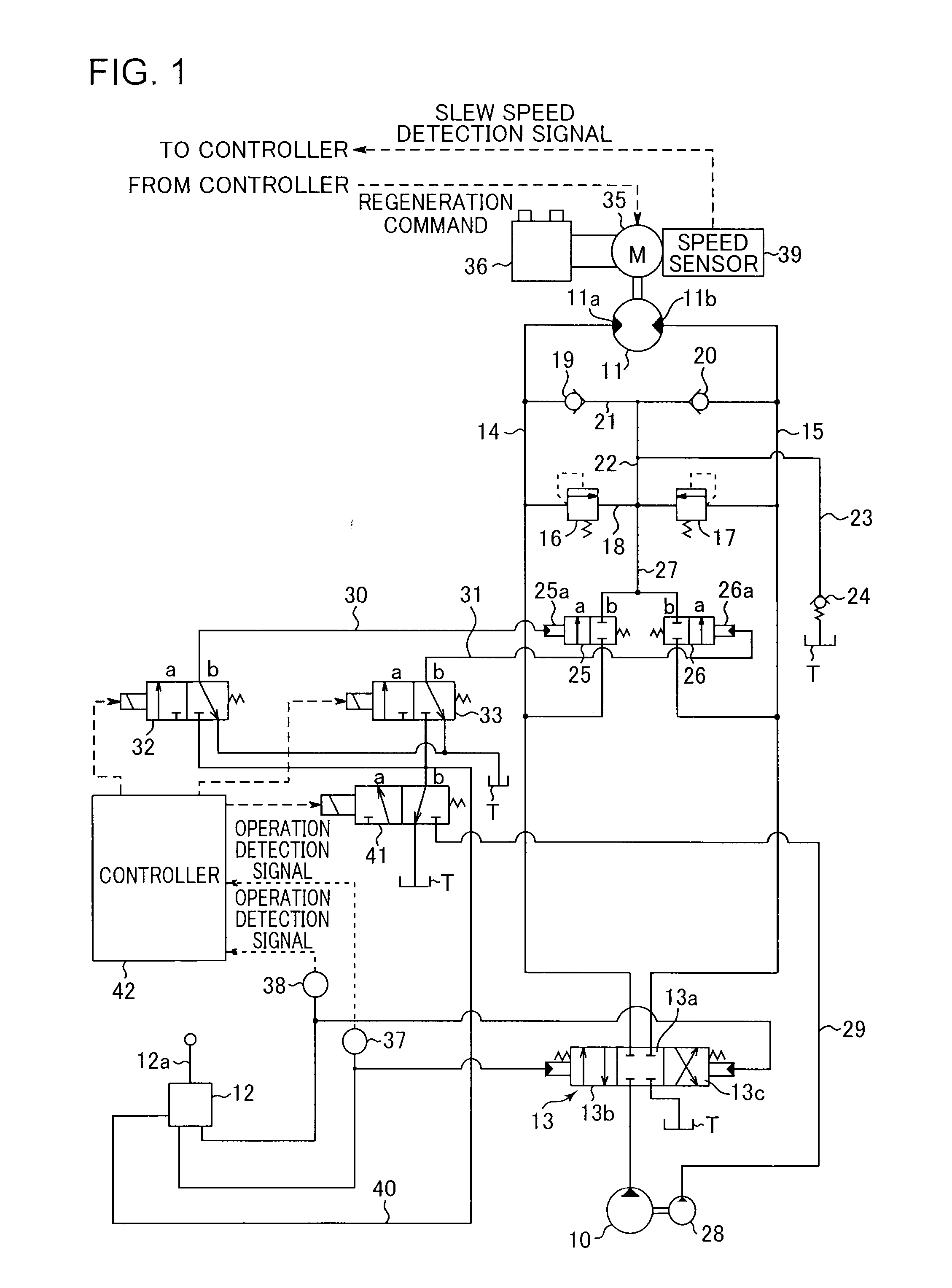
[0021]FIG. 1 shows a hydraulic circuit according to the present invention. The circuit includes: a hydraulic pump 10 as a hydraulic pressure source, which is driven by an engine not graphically shown; a slewing hydraulic motor 11 which is rotated by supply of hydraulic fluid discharged from the hydraulic pump 10 to drive the upper slewing body 2 to slew it, a remote-control valve 12 as a slewing operation device including a lever 12a to which an operation is applied to input a slewing command; and a control valve 13 which is a pilot-controlled selector valve capable of being operated by the remote-control valve 12 and is provided between the hydraulic motor 11 and a pair of the hydraulic pump 10 and a tank T.

[0022]The hydraulic motor 11 includes a left port 11a and a right port 11b which are first and second ports, respectively. When supplied with hydraulic fluid through the left port 11a, the hydraulic motor 11 discharges the hydraulic fluid through the right port 11b to leftward s...

second embodiment

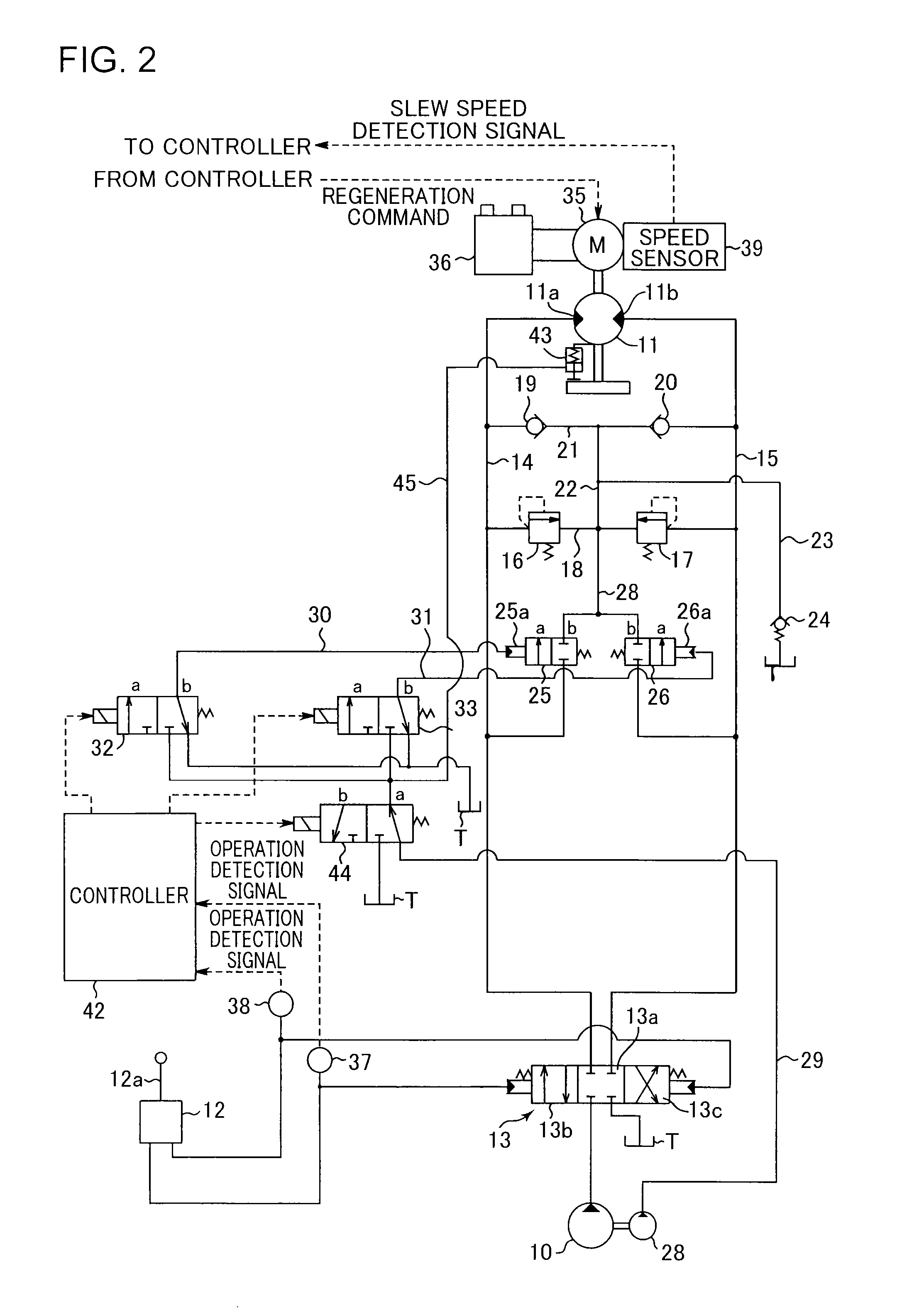
[0045]Next will be described the present invention, with reference to FIG. 2.

[0046]The work machine according to the second embodiment comprises, in addition to the components according to the first embodiment described above, a slewing parking brake 43 which mechanically holds the upper slewing body 2 in a stopped state, and also comprises a brake control valve 44 for controlling brake actuation / brake release of the slewing parking brake 43, in place of the lock valve 41 according to the first embodiment.

[0047]The slewing parking brake 43 is switchable between a braking state of holding the upper slewing body 2 and a brake release state of releasing the holding and is configured as a negative brake which is switched to the brake release state by hydraulic pressure outputted from the pilot pump 28. In addition to the pilot pump line 29 and the first and second-communication-valve pilot lines 32 and 33 on which respective communication selector valves 32 and 33 are provided, the pilo...


PUM


Abstract

A slewing-type working machine, including a base, an upper slewing body, a hydraulic motor slewing the upper slewing body, a hydraulic pump, a slewing operation device, a control valve controlling the hydraulic motor, pipe-lines connecting the hydraulic motor to the control valve, a hydraulic pressure source, communication valves switching communication and cutoff between the pipe-lines and a tank by pilot pressure, an electric motor, an electric storage device, communication selector valves on inlet sides of the communication valves, a switching control valve on an inlet side of the communication selector valves, and a controller. During slewing deceleration, the controller signals to switch the switching control valve to a connecting position and switch the communication selector valves to a pilot pressure supply position. In a slewing stopped state, the controller signals to switch the communication selector valves to a cutoff position and switch the communication valves to a communication cutoff position.

Description

TECHNICAL FIELD[0001]The present invention relates to a slewing-type working machine such as an excavator.BACKGROUND ART[0002]The background art of the present invention will be described using an excavator as an example.[0003]For example, as shown in FIG. 3, a general excavator comprises a crawler-type base carrier 1, an upper slewing body 2 mounted on the base carrier 1 so as to be capable of slewing around an axis X perpendicular to the ground, and an excavating attachment 3 attached to the upper slewing body 2. The excavating attachment 3 includes: a boom 4 capable of being raised and lowered; an arm 5 attached to a tip of the boom 4; a bucket 6 attached to a tip of the arm 5; and a boom cylinder 7, an arm cylinder 8, and a bucket cylinder 9 which are respective cylinders (hydraulic cylinders) for actuating the boom 4, the arm 5, and the bucket 6.[0004]FIG. 4 shows an example of a conventional hydraulic circuit for slewing the upper slewing body 2. The circuit includes: a hydrau...

Claims


Application Information

Patent Timeline
Patent Type & Authority Applications(United States)
IPC IPC(8): F15B15/02
CPCF15B2211/88F15B15/02E02F9/128E02F9/2095F15B2211/761F15B11/0406F15B2211/30565F15B2211/6316F15B2211/31558F15B2211/329F15B2211/853F15B2211/6355F15B2211/8636F15B2211/50545F15B2211/6336F15B2211/665F15B2211/7058F15B2211/5156E02F9/2217F15B21/14F15B2015/206F15B2211/715E02F9/2285E02F9/268E02F9/226
Inventor YAMASHITA, KOJIUEDA, KOJIKOMIYAMA, MASAYUKIYAMAZAKI, YOICHIROKAMIMURA, YUSUKE
Owner KOBELCO CONSTR MASCH CO LTD
Why Eureka
Try Eureka