Energy Recovering System of Hydraulic Lift Device for Battery Operated Industrial Trucks

Active Publication Date: 2007-12-06
NIPPON YUSOKI
View PDF11 Cites 4 Cited by
  • Summary
  • Abstract
  • Description
  • Claims
  • Application Information

AI Technical Summary

Benefits of technology

[0029] In this case, by allowing the hydraulic pump and/or hydraulic motor to operate at the rotation speed and flow rate of working fluid, with which the pump and/or motor operate with high efficiency, energy recovering efficiency is increased.
[0030] According to the present invention, by providing a hydraulic motor in a fluid path for recovering pressurized working fluid from a lift cylinder via a control valve to a working fluid reservoir tank so that the hydraulic motor is driven by the pressurized working fluid, and connecting an electric motor for driving a hydraulic pump to a hydraulic motor by means of a one-way clutch which performs torque transmission only from the hydraulic motor to the electric motor, rotation of the hydraulic motor is not transmitted to the hydraulic motor when the hydraulic pump is driven by the electric motor to raise a lift means. Therefore, useless energy cons

Problems solved by technology

With the energy recovering system, potential energy of the load can be effectively utilized, however, there is a problem that supplying pressurized oil to other actuators to actuate other devices is not possible by using the same hydraulic pump connected to the electric motor while operation of supplying work

Method used


Image

  • Energy Recovering System of Hydraulic Lift Device for Battery Operated Industrial Trucks
  • Energy Recovering System of Hydraulic Lift Device for Battery Operated Industrial Trucks
  • Energy Recovering System of Hydraulic Lift Device for Battery Operated Industrial Trucks

Examples


first embodiment

The First Embodiment

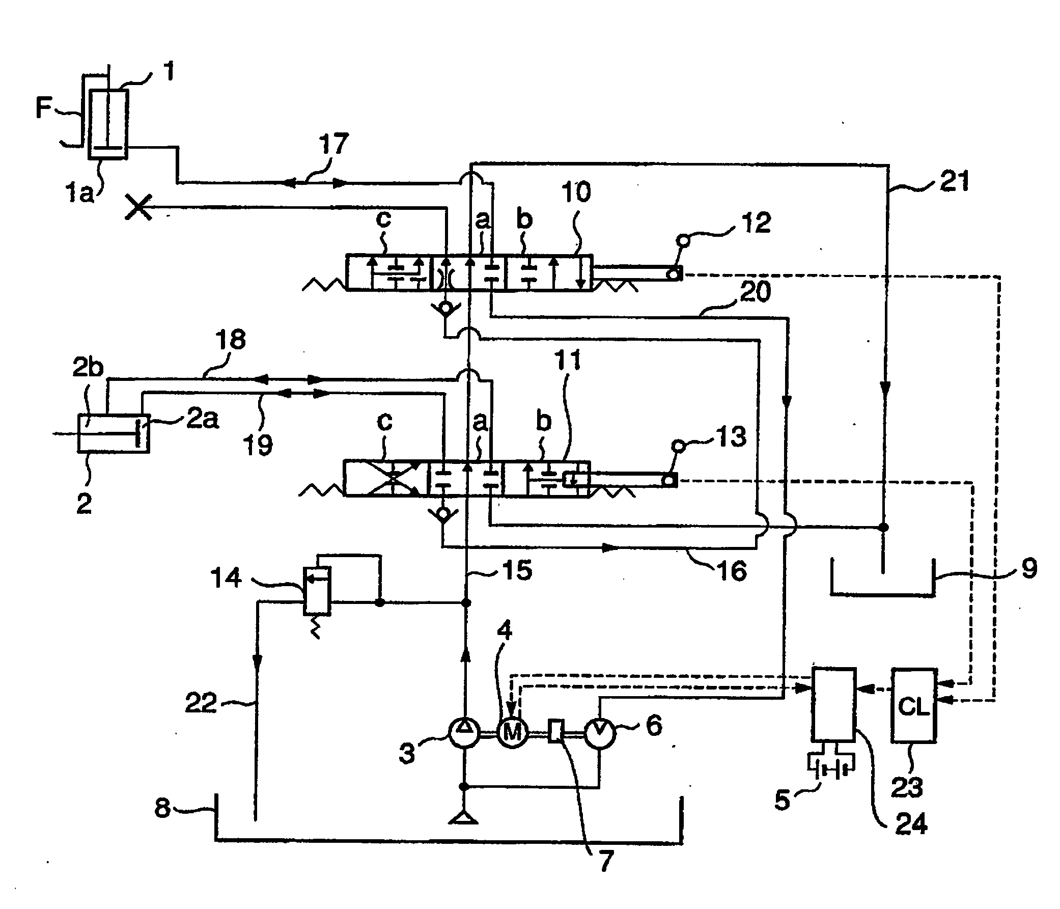
[0042]FIG. 1 is a schematic hydraulic lift circuit of the first embodiment of the invention applied to a hydraulic device for a forklift truck.

[0043] In FIG. 1, reference numeral 1 is a lift cylinder for lifting a fork F (lift means) of the forklift truck, 2 is a tilt cylinder for tilting a mast to which the fork F is installed, 3 is a hydraulic pump for supplying pressurized oil to the lift cylinder 1 and the tilt cylinder 2, 5 is a set of batteries for supplying electricity to an electric motor 4, 6 is a hydraulic motor which is disposed in a working oil recovering path 20 connected to a bottom oil chamber 1a of the lift cylinder 1 so that it is driven by pressurized oil returning from the bottom oil chamber 1a. The electric motor 4 is driven by the hydraulic motor 6 to be allowed to function as an electric motor, the generated AC power is converted into DC by means of an inverter 24 to charge the set of batteries 5 connected to the inverter 24.

[0044] Referen...

second embodiment

The Second Embodiment

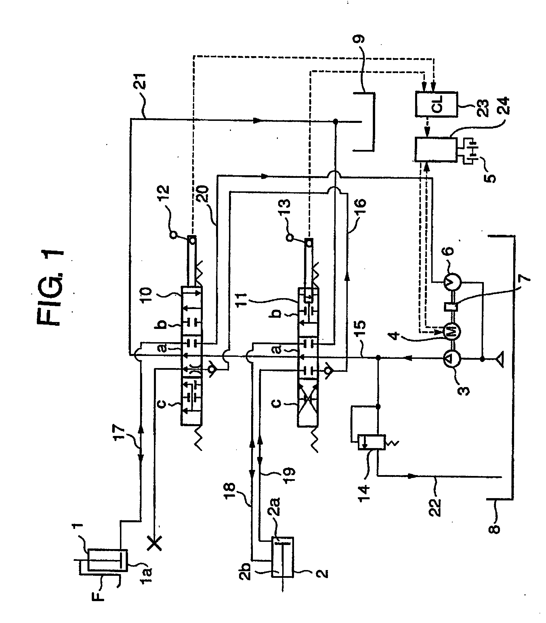
[0054] Next, the second embodiment of the invention will be explained with reference to FIGS. 2-4. FIG. 2 is a schematic hydraulic lift circuit of the second embodiment of the invention, FIG. 3 is a diagram showing the opening / closing velocity vs. time of the electromagnetic valve used in the second embodiment, and FIG. 4 is a diagram showing the discharge oil pressure variation of the hydraulic pump in the second embodiment.

[0055] In the second embodiment, a return path 31 connected to the discharge side of the hydraulic pump 3 and an electromagnetic valve 30 disposed in the return path 31 are further added to the first embodiment as shown in FIG. 2 to allow the pressurized working oil to be returned to the oil reservoir tank 8. The rest of the construction is the same as that of the first embodiment, and constituent parts the same as those of the first embodiment are indicated by the same reference numerals.

[0056] The electromagnetic valve 30 opens the retur...

third embodiment

The Third Embodiment

[0062] Next, the third embodiment of the invention will be explained with reference to FIGS. 5-6. FIG. 5 is a schematic hydraulic lift circuit of the third embodiment, and FIG. 6 is a diagram showing the inlet oil pressure variation of the hydraulic motor in the third embodiment.

[0063] In the third embodiment, a branch path 40 branching from the upstream zone of the discharge side of the hydraulic motor 6 with its end part being immersed in the working oil in the oil reservoir tank 8 and a check valve 41 disposed in the branch path 40 to prevent working oil from flowing from the recovering path 20 to the oil reservoir tank 8, are further added to the second embodiment, as shown in FIG. 5. The rest of the construction is the same as that of the second embodiment.

[0064] As shown in FIG. 6, when lowering operation of the fork F is finished, the control valve 10 is closed at once. On the other hand, the hydraulic motor 6 continues to rotate for some time due to rot...


PUM


Abstract

An energy recovering system of a hydraulic lift device for a battery operated industrial truck. With the system, working oil can be supplied to other hydraulic actuators while energy recovering operation is performed by the hydraulic lift device, and energy recovering efficiency is increased. A hydraulic motor (6) is disposed in a fluid path for recovering pressurized working fluid from a lift cylinder (1) via a control valve (10) to a working fluid reservoir tank (8) so that the hydraulic motor (6) is driven by the pressurized working fluid returning from the lift cylinder (1). The hydraulic motor (6) is connected to an electric motor (4) for driving a hydraulic pump (3), which supplies pressurized fluid to the lift cylinder (1), by means of a one-way clutch (7) which performs torque transmission only from the hydraulic motor (6) to the electric motor (4).

Description

TECHNICAL FIELD [0001] The present invention relates to an energy recovering system of a hydraulic lift device for battery operated industrial tracks such as a forklift truck or the like, specifically to an energy recovering system for recovering the potential energy generated by a hydraulic lift device having a hydraulic pump for supplying pressurized working fluid to a lift cylinder to lift and lower a load on a lift means, an electric motor for driving the hydraulic pump, a hydraulic motor for recovering the potential energy of the load by allowing the hydraulic motor to be driven by the pressurized working fluid returning from the lift cylinder when the load is lowered, whereby the hydraulic pump is connected directly to the electric motor and the hydraulic motor is connected to the electric motor by means of a one-way clutch so that the electric motor is driven by the hydraulic motor to be allowed to function as an electric generator, thus the hydraulic pump, electric motor, an...

Claims


Application Information

Patent Timeline
IPC IPC(8): B66F9/24
CPCB66F9/22F15B2211/88F15B2211/3111F15B21/14Y02P80/10
Inventor FUTAHASHI, KENSUKESATOU, HIROSHIKAWAGUCHI, MASATAKAEGUCHI, FUJIOHONDA, TOSHIYUKIOGINO, KEIZOYUGUCHI, SHINGOKAWASHIMA, KAZUHITOAKAO, MICHIRO
Owner NIPPON YUSOKI
Why Eureka
Try Eureka