Power train system for vehicle

a technology for power trains and vehicles, applied in the direction of engine-driven generators, instruments, transportation and packaging, etc., can solve the problems of deterioration in the efficiency of collecting energy, cumbersome and complicated outer structure of engines, and difficulty in mounting those component parts, so as to improve the energy recovery efficiency of expanders and the operation efficiency of these components

Inactive Publication Date: 2006-03-02
DENSO CORP
View PDF8 Cites 18 Cited by
  • Summary
  • Abstract
  • Description
  • Claims
  • Application Information

AI Technical Summary

Benefits of technology

[0019] It is conceivable that the auxiliary unit is comprised of an air-conditioning compressor to allow the same to be used for constructing a refrigeration cycle. Under such a situation, an expander may be disposed in mid-course of a coolant passage, through which coolant flows, to expand coolant in reduced pressure while converting expansion energy to mechanical energy for recovery of energy for thereby permitting the resulting mechanical energy, recovered with the expander, to operate the compressor and the motor generator. This allows mechanical energy, collected with the expander, to assist the operations of the compressor and the motor generator, resulting in improvement over operating efficiencies of these component parts.
[0020] A heat recovery device may be disposed in the coolant flow passage at a position upstream of the expander for collecting waste heats. This allows the improvement over an energy recovery efficiency of the expander.

Problems solved by technology

With such a structure, however, the auxiliary unit and associated power cut-off mechanism are mounted on a periphery of the engine, making a peripheral structure of the engine cumbersome and complicated.
Also, considering a structure wherein the respective component parts are installed in a limited installation space around the engine, inconvenience may occur with the resultant difficulty in mounting those component parts.
However, since the existing system takes the form of a structure wherein energy is collected via a transmission connected to an engine output shaft, causing issues with deterioration in efficiency of collecting energy.

Method used


Image

  • Power train system for vehicle
  • Power train system for vehicle
  • Power train system for vehicle

Examples


first embodiment

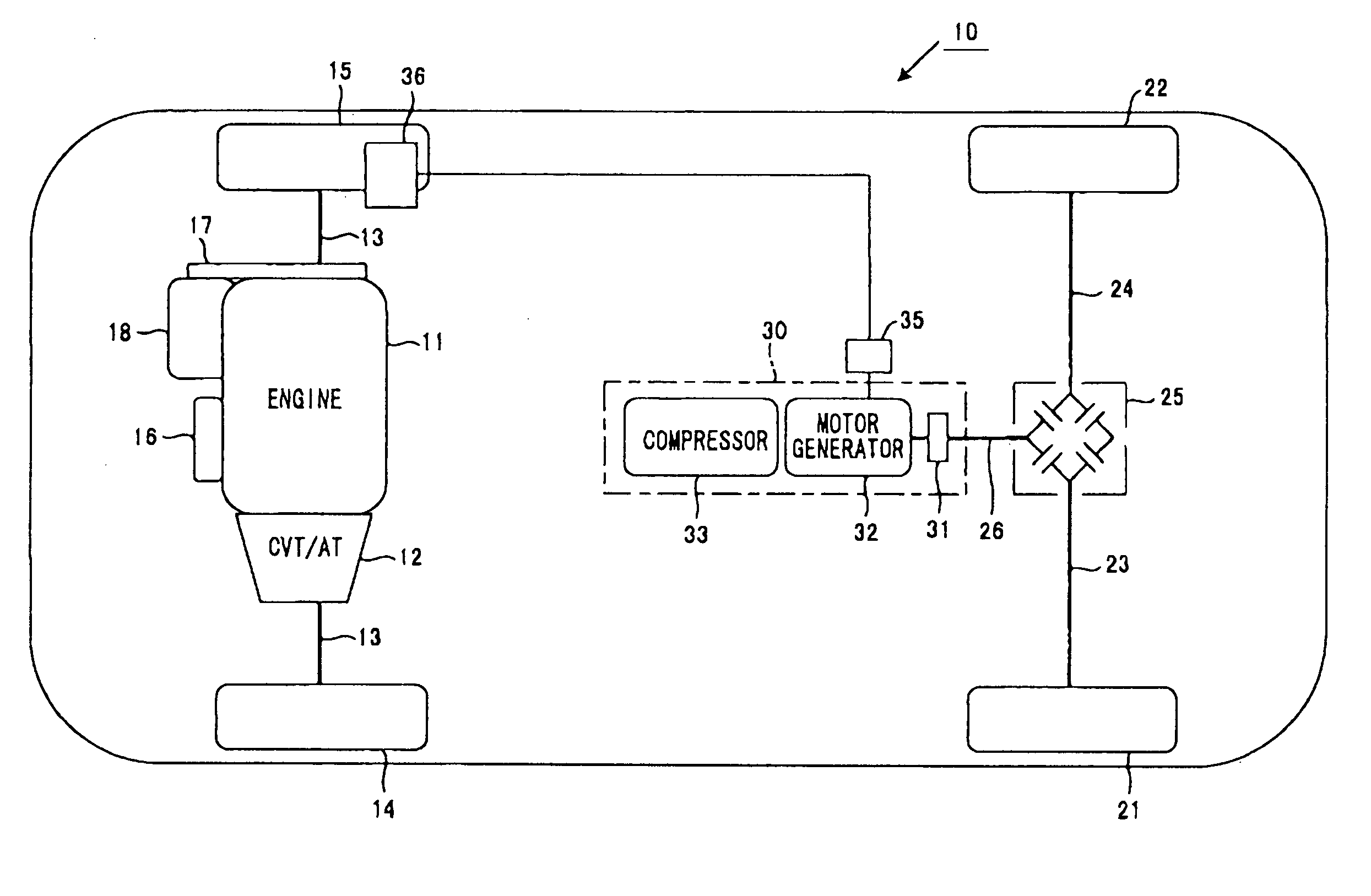
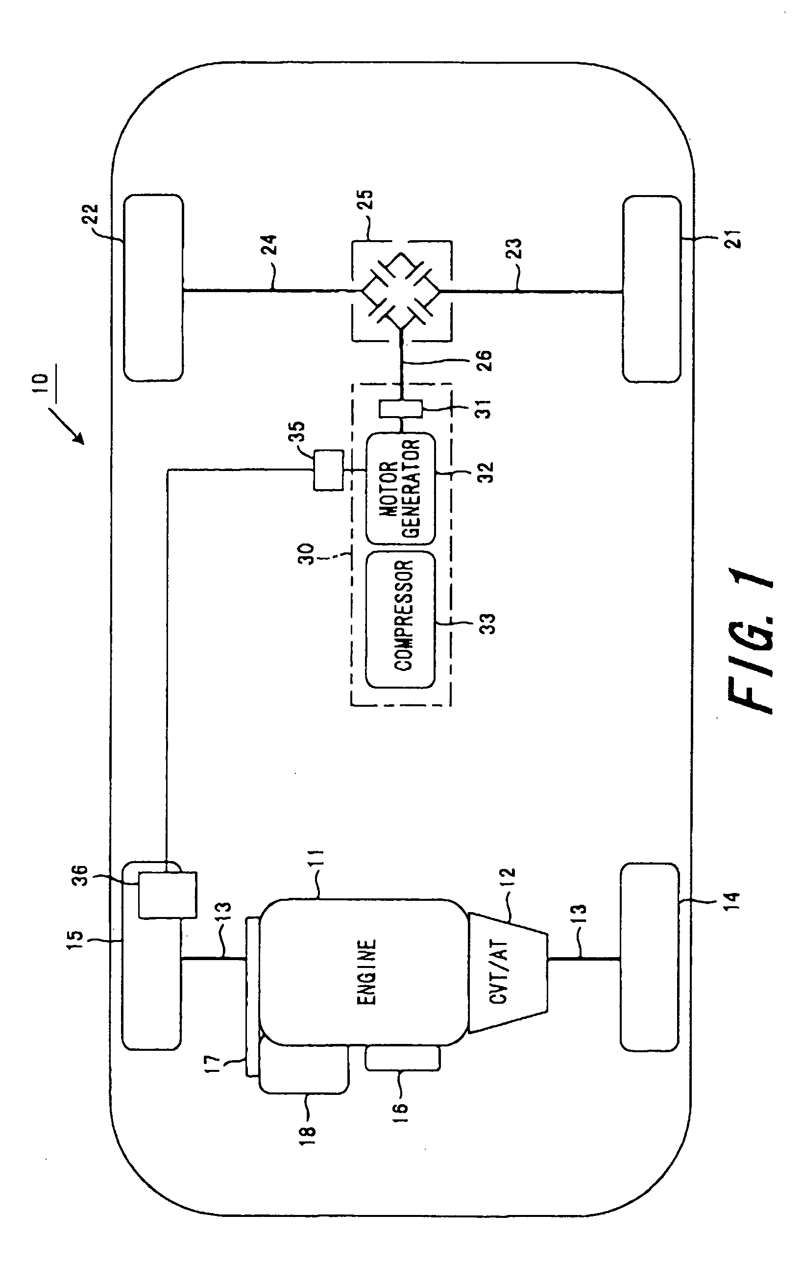
[0031] A first embodiment according to the present invention will now be described below with reference to the accompanying drawings. The present embodiment is described in conjunction with an exemplary wherein the presently filed embodiment is concretized in a so-called hybrid vehicle, which takes the form of a power drive source including an engine and an electric motor, to run with either one of resulting powers. FIG. 1 is a view showing a schematic structure of a vehicle system of the presently filed embodiment. In addition, in FIG. 1, the left and right sides of the drawing represent the front and rear of a vehicle, respectively.

[0032] In FIG. 1, a vehicle 10 includes a front section in which an engine 11, playing a role as a power drive source, and a transmission 12, composed of a CVT (Continuously Variable Transmission) and an AT (Automatic Power Transmission), etc., are connected in series to allow an output of the engine 11 to be transmitted to axles 13 via the transmissio...

second embodiment

[0049] A second embodiment takes the form of a structure wherein an expander, by which coolant expands in reduced pressure to convert expansion energy into mechanical energy upon recovery, is disposed in mid-course of a coolant passage through which coolant (such as, for instance, carbon dioxide) flows to allow mechanical energy, recovered from the expander, to be used for driving the compressor and the motor generator.

[0050]FIG. 3 shows a vehicle system of the second embodiment, which differs from that of FIG. 1 in that the vehicle additionally incorporates a coolant circulation circuit (in refrigeration cycle) for a vehicle air-conditioning unit. Also, the compressor 33, by which coolant is compressed, is of the nature, which is disposed in the mid-course of a coolant delivery pipe 54, and shown as the vehicle auxiliary unit 30 together with the motor generator 32 for the sake of convenience as in FIG. 1.

[0051] With a structure shown in FIG. 3, the expander 51, an evaporator (va...

third embodiment

[0055] Now, a vehicle system of a third embodiment is described. FIG. 4 is a view showing a schematic structure of the vehicle system of the presently filed embodiment. Also, in FIG. 4, a left side represents a front of a vehicle and a right side represents a rear of the vehicle.

[0056] In FIG. 4, two power generation devices are incorporated in back and forth areas of a vehicle 60 and a main power block D1 is mounted in an area closer to front wheels as a first power generation device and a subsidiary power block D2 is installed in an area closer to rear wheels as a second power generation device. The vehicle 60 runs with powers created by these two power blocks D1, D2.

[0057] In particular, the vehicle 60 has a front section, provided with two left and right front wheels 61, 62 as main drive wheels, and the main power block D1 is coupled to axles 63 to which the front wheels 61, 62 are connected. The main power block D1 is comprised of an engine 64, playing a role as a main power ...


PUM


Abstract

A power train system for a vehicle is disclosed, in which the vehicle is provided with front wheels and rear wheels, one of which are main drive wheels and the other of which are subsidiary drive wheels. The system comprises a first power source arranged to power the main drive wheels and a second power source arranged to power the subsidiary drive wheels. The system further comprises a wheel coupling shaft mechanically coupled with the subsidiary drive wheels and a power distribution device mechanically coupled with the wheel coupling shaft and the second power source to perform power distributions to and from the wheel coupling shaft.

Description

CROSS REFERENCE TO RELATED APPLICATIONS [0001] The present application relates to and incorporates by reference Japanese Patent applications No. 2004-256010 filed on Sep. 2, 2004 and No. 2005-081208 filed on Mar. 22, 2005. BACKGROUND OF THE INVENTION [0002] 1. Field of the Invention [0003] The present invention relates to a power train system for a vehicle wherein power sources are mounted for front and rear wheels of a vehicle, respectively, to enable the vehicle to run with resulting powers. [0004] 2. Description of the Related Art [0005] In the related art, a large number of proposals have heretofore been made to provide a vehicle system that includes an engine and a motor generator as power sources of a vehicle to allow the vehicle to run with at least either one of resulting powers. For instance, Japanese Patent Provisional Publication No. 11-147424 discloses a structure, wherein a motor generator is connected to a crankshaft of an engine and an auxiliary unit (also, called “ac...

Claims


Application Information

Patent Timeline
Patent Type & Authority Applications(United States)
IPC IPC(8): G06F17/00B60K6/365B60K6/44B60K6/52B60K6/543B60K6/547B60K17/356B60L50/16B60W10/30B60W20/00
CPCB60H1/3222B60K6/52B60W10/06Y02T10/6286B60W10/30B60W20/00Y02T10/6265B60W10/08Y02T10/62B60W20/10B60W10/26
Inventor ABE, TETSUYAEGAMI, TSUNEYUKI
Owner DENSO CORP
Why Eureka
Try Eureka