Contact bearing

a technology of contact bearings and bearings, which is applied in the direction of bearing unit rigid support, machine/engine, light and heating apparatus, etc., can solve the problems of increasing friction, and achieve the effect of high performance characteristics and increased service li

Inactive Publication Date: 2006-07-18
METHODE ELETRONICS INC
View PDF96 Cites 31 Cited by
  • Summary
  • Abstract
  • Description
  • Claims
  • Application Information

AI Technical Summary

Benefits of technology

[0016]Various embodiments of the present invention provide certain advantages and overcome certain drawbacks of prior contact bearings.
[0017]Embodiments of the invention may not share the same advantages, and those that do may not share them under all circumstances. This being said, the present invention provides numerous advantages including the noted advantage of increased service life and / or high performance characteristics.

Problems solved by technology

Wear is often caused by an increase in friction, which is the resistance to relative motion between objects.
Some causes of friction contributing to wear include loose particles plowing (e.g. cutting) into the bearing and asperity (e.g., surface irregularities) interactions at the surfaces of the bearing.

Method used


Image

  • Contact bearing
  • Contact bearing
  • Contact bearing

Examples


Embodiment Construction

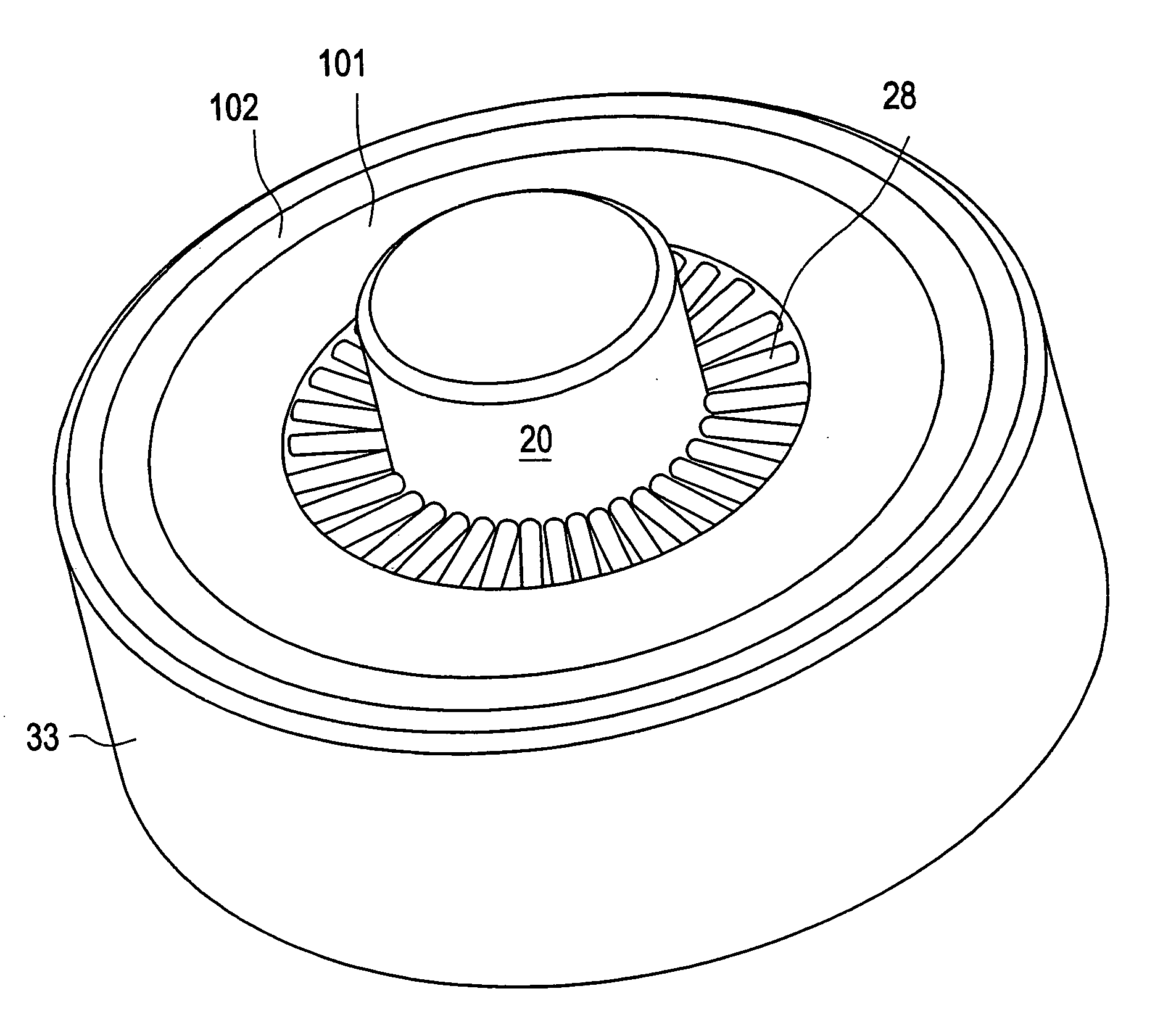
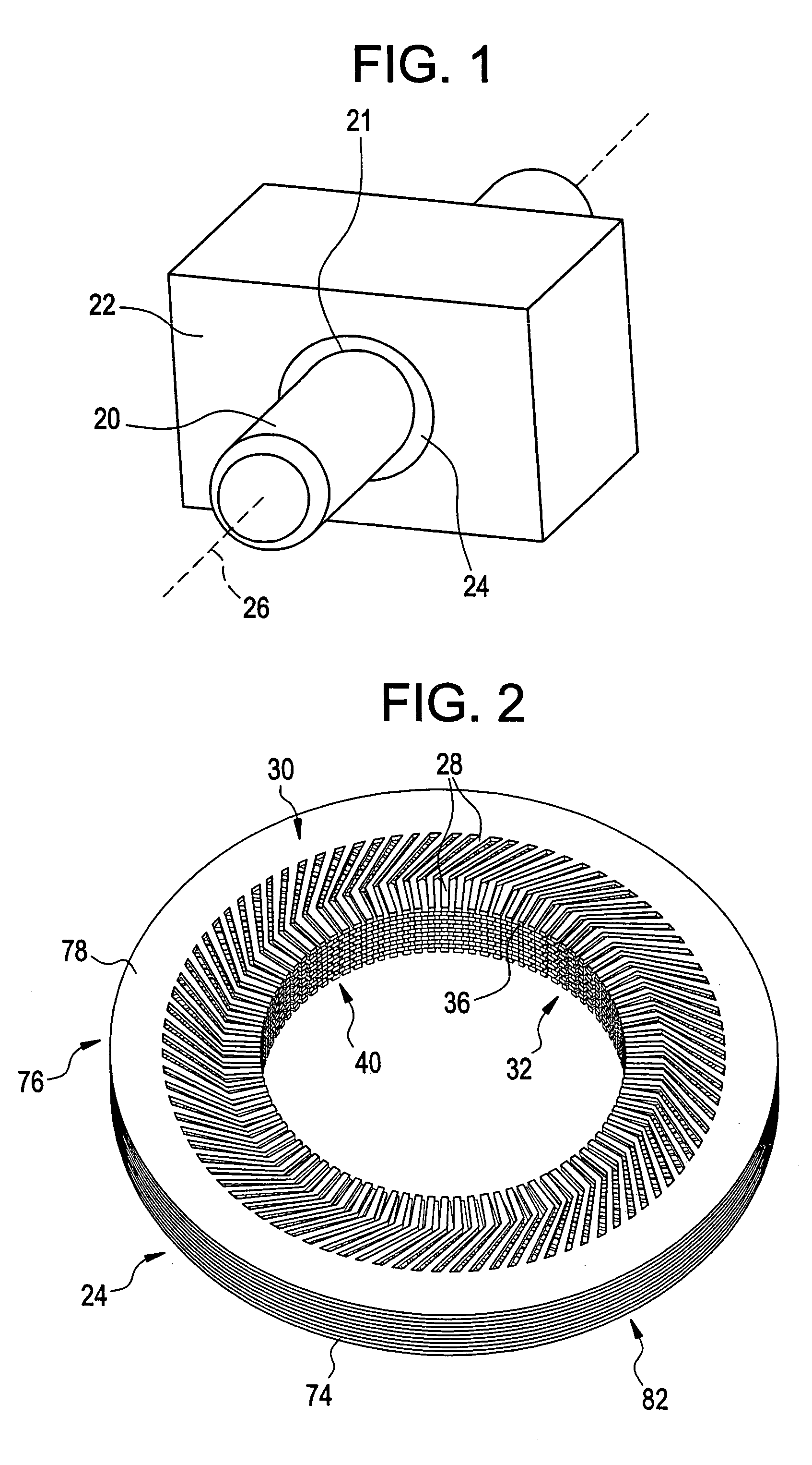
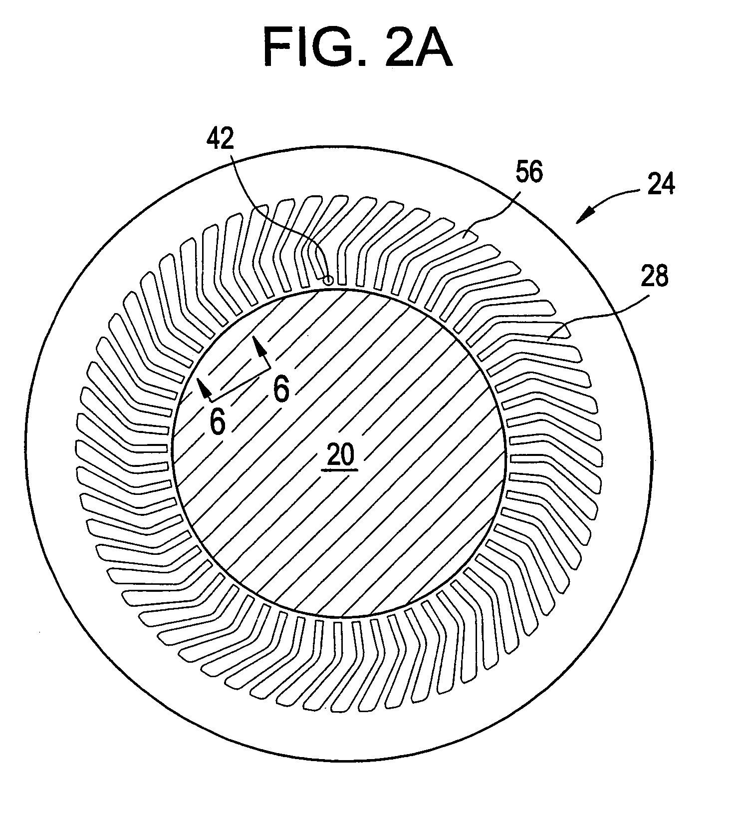
[0046]The bearing of the present invention is adapted to support an opposed bearing surface and allow relative movement there between. The bearing is constructed to have a long life by incorporating a surface that addresses many causes of friction and wear.

[0047]In one aspect, as described in commonly assigned co-pending U.S. patent application Ser. No. 10 / 167,070, which is hereby incorporated herein by reference in its entirety, the bearing may include a locally compliant surface formed of a plurality of support members extending from a base. Together, the plurality of support members can support a load applied to the base through an opposed bearing surface while allowing sliding movement there between. The support members can move or flex independently to accommodate irregularities, such as asperities or loose particles located between the support members and the opposed bearing. In this sense, some “local” areas of the bearing may be considered compliant so as to accommodate the ...


PUM


Abstract

A bearing adapted to support and allow controlled relative movement with an opposed bearing surface. The bearing is constructed to have a long life by incorporating a surface that addresses many causes of friction and wear. The bearing includes a plurality of support members extending from a base. Together, the plurality of support members can support a load applied to the base through an opposed bearing surface. Additionally, the plurality of support members allow sliding modes of motion between the opposed bearings. These support members can move independently to accommodate irregularities located between the support member and the opposed bearing, such that plowing is reduced and wear to the bearings is minimized. The support members may also be configured to allow certain non-sliding modes of motion between opposed bearing surfaces while resisting other non-sliding modes of motion.

Description

CROSS REFERENCE TO RELATED APPLICATIONS[0001]This application also claims the benefit of and is a continuation-in-part of U.S. patent application Ser. No. 10 / 167,070, filed on Jun. 11, 2002, which claims priority to U.S. Provisional Patent Application No. 60 / 297,427, filed Jun. 11, 2001. This application claims the benefit of U.S. Provisional Patent Application Nos. 60 / 363,696, filed on Mar. 12, 2002, and 60 / 416,872, filed on Oct. 8, 2002.FIELD OF THE INVENTION[0002]The present invention relates to a contact bearing and more particularly to a sliding contact bearing with an increased service life.BACKGROUND OF INVENTION[0003]Bearings are used in a wide variety of applications. Representative example applications include simple door hinges, internal combustion engines, heavy duty construction equipment, and other applications that may subject a bearing to corrosive materials, abrasive particles, or non-lubricated environments. In these applications and others, bearings support contac...

Claims


Application Information

Patent Timeline
Patent Type & Authority Patents(United States)
IPC IPC(8): F16C33/02F01D11/02F16C17/00F16C23/04F23J3/00E05D5/14F16C17/24F16C27/02F16C29/00F16C29/02F16C33/00F16C33/10F16C33/20F16C33/26F16J15/32
CPCF16C27/02F16C29/002F16C29/02F16C17/246F16C33/26F16J15/3288F16J15/3292F16C33/106E05D5/14B33Y80/00
Inventor SUH, NAM P.SWEETLAND, MATTHEW
Owner METHODE ELETRONICS INC
Why Eureka
Try Eureka