
Housing with conductor bus for a disconnecting apparatus

a disconnecting apparatus and conductor bus technology, applied in the direction of contact mechanisms, circuit-breaking switches, battery cutoff switches, etc., can solve the problems of difficult to check whether the disconnecting apparatus has tripped, restricted employment, etc., and achieve the effect of preventing cracking and reducing the danger of cracking

Inactive Publication Date: 2006-07-18
AUTOLIV DEV AB +1
View PDF15 Cites 23 Cited by
  • Summary
  • Abstract
  • Description
  • Claims
  • Application Information

AI Technical Summary

Benefits of technology

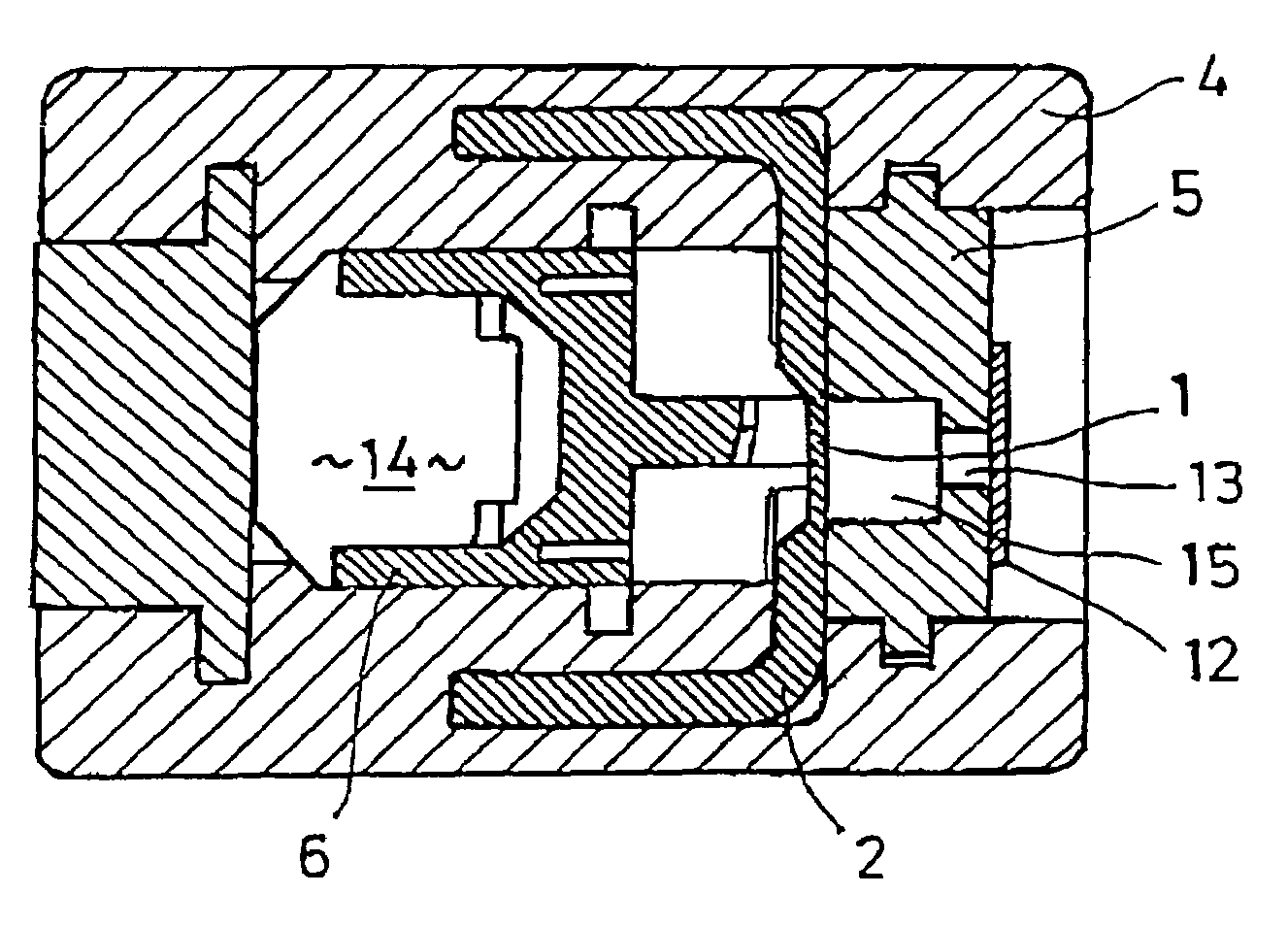
[0006]Because a recess is arranged in the locking bolt, which recess transpicuously connects the receiving space with the atmosphere, stresses that act on the locking bolt and the housing during the disconnection process are diminished so that cracking is prevented or at least the danger of cracking is reduced.
[0007]What is more, the recess, which transpicuously connects the receiving space with the atmosphere, enables the operator to determine easily whether a severance of the conductor bus has taken place or whether the disconnecting apparatus has tripped.
[0009]The recess or hole is advantageously covered by a transparent material. This has the advantage of preventing foreign bodies (dust, chips) penetrating into the receiving space via the recess. Further, the ionization spark arising during the disconnection process is encapsulated and the danger of spontaneous ignition of substances capable of being ignited by electric sparks is prevented.

Problems solved by technology

This is generally associated with costs and is disadvantageous in that the component volume is increased and thus employment may be restricted.
What is more, it is not easy to check whether the disconnecting apparatus has tripped, that is, a severance of the conductor bus has taken place.

Method used


Image

  • Housing with conductor bus for a disconnecting apparatus
  • Housing with conductor bus for a disconnecting apparatus

Examples


Embodiment Construction

[0013]Further features are shown in the drawings, which are described in what follows.

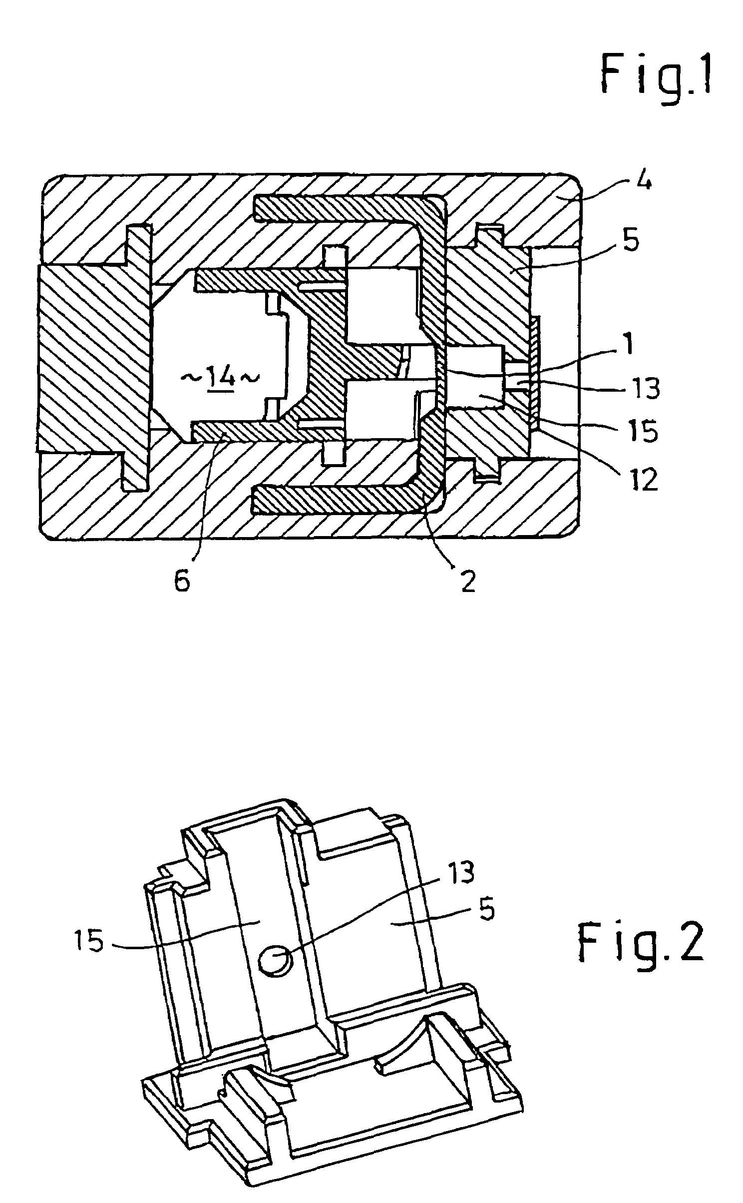
[0014]FIG. 1 shows a housing 4 of a disconnecting apparatus, in which a conductor bus 2 is arranged. Arranged in axially displaceable fashion in housing 4 is a cutting chisel 6, which is movable by a firing element 14 or its pyrotechnic charge (propellant gas) in the direction of bus 2. For the axial fixation of conductor bus 2 in housing 4, conductor bus 2 is restrained by a locking bolt 5 (see also FIG. 2). Let into this locking bolt 5 is a receiving space 15, which adjoins predetermined cut position 1 of conductor bus 2 and is arranged on the side of conductor bus 2 opposite to cutting chisel 6, so that receiving space 15 is located between bus 2 and locking bolt 5. On firing of firing element 14, cutting chisel 6 is accelerated toward conductor bus 2 and severs conductor bus 2 at predetermined cut position 1 by a bending process. The bent-over part of bus 2 is here bent over into receiving spac...


PUM

PropertyMeasurementUnit
Electrical conductivityaaaaaaaaaa
Areaaaaaaaaaaa
Transparencyaaaaaaaaaa

Abstract

A pyromechanical disconnecting apparatus, in particular for battery shutoff in a motor vehicle, includes a housing (4) in which there is arranged an electrically conductive conductor bus (2), which is fashioned so as to be severable at a predetermined cut position (1) by a cutting chisel (6) driven by a pyrotechnic propellant charge. The conductor bus (2) is clamped in on its side facing away from the cutting chisel (6) by a locking bolt (5) inserted into the housing (4), and a receiving space (15) is arranged in the locking bolt (5) in the region of the predetermined cut position (1), into which receiving space the cutting chisel (6) bends the region of the conductor bus (2) severed by it, and the locking bolt (5) forms an external surface of the housing (4). In order to diminish cracking of the locking bolt and housing and for purposes of inspection to determine whether the disconnecting apparatus has tripped, it is proposed that a recess (13) be arranged in the locking bolt (5), which recess transpicuously connects the receiving space (15) with the atmosphere.

Description

BACKGROUND OF THE INVENTION[0001]This invention relates to a pyromechanical disconnecting apparatus, in particular for battery shutoff in a motor vehicle, having a housing in which there is arranged an electrically conductive conductor bus, which is fashioned so as to be severable at a predetermined cut position by a cutting chisel driven by a pyrotechnic propellant charge, the conductor bus is clamped in on its side facing away from the cutting chisel by a locking bolt inserted into the housing, and a receiving space is arranged in the locking bolt in the region of the predetermined cut position, into which receiving space the cutting chisel bends the region of the conductor bus severed by it, and the locking bolt forms an external surface of the housing.[0002]Such a pyromechanical disconnecting apparatus is shown by DE 103 37 958 A1.[0003]By reason of mechanical stressing / loading during the disconnection process, it is impossible to rule out cracking of the locking bolt and housin...

Claims


Application Information

Patent Timeline
IPC IPC(8): H01H85/00B23D15/14B60R16/02B60R16/03H01H39/00
CPCH01H39/006B23D15/145B60R16/03H01H2039/008H01H2009/0292
Inventor KORDEL, GERHARDKNAUSS, JURGEN
Owner AUTOLIV DEV AB
Learn More