Plasma display panel and method for driving the same

a technology of display panel and plasma, which is applied in the direction of identification means, pulse techniques, instruments, etc., can solve the problems of large power consumption of pdp, significant energy loss in pdp, and greater energy loss, so as to minimize the rise time of sustain pulse and reduce the power consumption of the drive circuit

Inactive Publication Date: 2006-07-18
LG ELECTRONICS INC
View PDF7 Cites 4 Cited by
  • Summary
  • Abstract
  • Description
  • Claims
  • Application Information

AI Technical Summary

Benefits of technology

[0014]Therefore, the present invention has been made in view of the above problems, and it is an object of the present invention to provide an energy recovery circuit of a PDP and a drive method thereof in which a sustain voltage used in the conventional energy recovery circuit is reduced by one half such that the amount of power consumed by a drive circuit is reduced, and in which a booster drive circuit is used during charging of a panel capacitor to thereby minimize a rise time of a sustain pulse is minimized.

Problems solved by technology

The biggest drawback of the PDP is its large consumption of power.
When charge / discharge occurs in this manner in the PDP, although there is no energy consumption by only the capacity load of the panel, there is significant energy loss in the PDP since the drive pulse is generated using DC power.
In particular, if an excessive current flows in the cells during discharge, an even greater energy loss occurs.
This energy loss causes an increase in the temperature of switch elements, and, in the worst case, the switch elements may be destroyed by such a temperature increase.
Further, since a relatively large sustain voltage is supplied to the panel capacitor, power consumption is increased.

Method used


Image

  • Plasma display panel and method for driving the same
  • Plasma display panel and method for driving the same
  • Plasma display panel and method for driving the same

Examples


Embodiment Construction

[0027]Preferred embodiment of the present invention will be described in a more detailed manner with reference to the drawings.

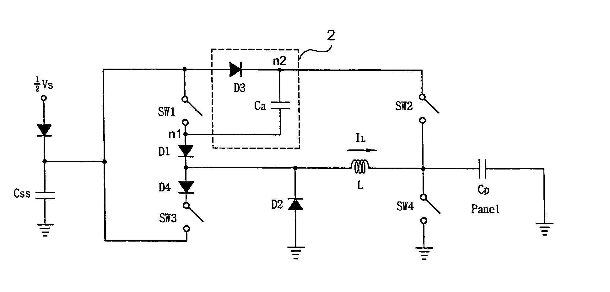
[0028]FIG. 3 is a circuit diagram of an energy recovery circuit according to the present invention. With reference to FIG. 3, the energy recovery circuit of the present invention includes an external ½ sustain voltage source having a voltage that is one half of a sustain voltage, an external capacitor for recovering energy when energy stored in a panel capacitor is discharged, an inductor for charging and discharging the panel capacitor, a multiple voltage circuit including an auxiliary capacitor for generating the sustain voltage using the voltage of the ½ sustain voltage source, a first switch that is turned on a first time such that energy is charged to the inductor and turned on a second time such that the sustain voltage is supplied to the panel capacitor, a second switch that is turned on at the same time the first switch is turned on for the second ti...


PUM


Abstract

An energy recovery circuit of a plasma display panel and a drive method thereof are disclosed. A plasma display panel according to the present invention comprises an inductor for charging or discharging the panel capacitor, inductor charge path means which provides a path through which energy is charged to the inductor, panel capacitor charge path means which provides a path through which the panel capacitor is charged with the energy charged in the inductor, panel capacitor discharge path means which provides a path through which the panel capacitor is discharged, auxiliary storage means which stores energy if the substantially fully discharged state of the panel capacitor is maintained and supplies the energy to the panel capacitor if the substantially fully charged state of the panel capacitor is maintained, and potential sustain means connected to the inductor and the panel capacitor, wherein the potential sustain means includes switch means connected between the auxiliary storage means and the panel capacitor and another switch means connected between a ground potential and the panel capacitor.

Description

TECHNICAL FIELD[0001]The present invention relates to a plasma display panel (hereinafter, referred to as “PDP”). More particularly, the present invention relates to plasma display panel and method for driving the same in which the energy recovery circuit uses a booster drive circuit that is able to reduce a sustain voltage by half to thereby reduce the amount of energy consumed by a drive circuit of the PDP and reduce a rise time of a sustain pulse.BACKGROUND OF THE INVENTION[0002]The biggest drawback of the PDP is its large consumption of power. In order to reduce the amount of power consumed by the PDP, it is necessary to enhance its illumination efficiency and to minimize the unnecessary use of power (not directly related to discharge) that occurs during the drive process.[0003]The AC PDP utilizes surface discharge occurring on a surface of a dielectric substance that is deposited on electrodes. In the AC PDP, in order to perform sustain discharge of tens of thousands to several...

Claims


Application Information

Patent Timeline
Patent Type & Authority Patents(United States)
IPC IPC(8): G09G3/10G09G3/20G09F9/313G09G3/296H01J17/49H03K17/00H03K17/687
CPCG09G3/2942G09G3/2965G09G2310/066G09G3/296
Inventor CHOI, JEONG PIL
Owner LG ELECTRONICS INC
Why Eureka
Try Eureka