Color laser printer

a laser printer and color technology, applied in the field of color laser printers, can solve the problems of lowering the printing quality, jitter and periodic oscillation, and the color laser printer configured as described above has not yet become popular,

Inactive Publication Date: 2006-07-18
HEWLETT PACKARD DEV CO LP
View PDF15 Cites 91 Cited by
  • Summary
  • Abstract
  • Description
  • Claims
  • Application Information

AI Technical Summary

Problems solved by technology

The color laser printer configured as described above has not yet become popular due to high manufacturing costs.
A manufacturing cost of the LSUs is a largest percentage of a total cost of the color laser printer.
Another problem with this type of color laser printer is that a jitter and a periodic oscillation occur when a spindle motor drives the rotary polygon mirror for each color, and vary according to each LSU.
This causes four different color lines to be printed along different scanning lines when a user desires a single line to be printed on a paper sheet, thus lowering a printing quality.
However, this process increases the manufacturing costs.
However, as is well known, f-θ lenses of the large thickness are more difficult to manufacture.
Overall, this construction increases the manufacturing and assembly costs.
Further, compared with the color laser printer using the four LSUs, this color laser printe...

Method used


Image

  • Color laser printer
  • Color laser printer
  • Color laser printer

Examples


Embodiment Construction

[0036]Reference will now be made in detail to the present preferred embodiments of the present invention, examples of which are illustrated in the accompanying drawings, wherein like reference numerals refer to the like elements throughout. The embodiments are described in order to explain the present invention by referring to the figures.

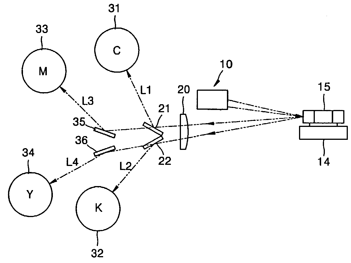
[0037]Referring to FIG. 4, a color laser printer according to an embodiment includes a lighting unit 10 having a plurality of light sources emitting S-polarized and P-polarized beams, a rotary polygon mirror 15 reflecting the S- and P-polarized beams emitted from the lighting unit 10, an f-θ lens 20 focusing the S- and P-polarized beams reflected by the rotary polygon mirror 15, and first and second polarization beam splitters 21 and 22 transmitting or reflecting the S- and P-polarized beams passing through the f-θ lens 20 depending on a direction of polarization of the S- and P-polarized beams.

[0038]As shown in FIG. 5, the lighting unit 10 include...


PUM


Abstract

A color laser printer producing a color image using a single laser scanning unit includes a lighting unit including first and second laser diodes emitting beams of one polarization, a polarization prism transmitting or reflecting incident beams depending on a direction of polarization, and third and fourth laser diodes disposed in a different direction from the first and second laser diodes with respect to the polarization prism, a rotary polygon mirror that reflects the beam emitted along the same path from the lighting unit, an f-θ lens that focuses the beam reflected by the rotary polygon mirror, first and second polarization beam splitters, each of which transmits or reflects the beam passing through the f-θ lens depending on the direction of the polarization, and first through fourth photoconductive units on which the beams reflected and transmitted through the first and second polarization beam splitters are incident. In the color laser printer, lengths of optical paths between the f-θ lens and each of the first through fourth photoconductive units are equal. The color laser printer is constructed such that a plurality of light sources emitting the beams of one polarization are arranged separately and the beams emitted from the light sources are combined by the polarization prism to enter the f-θ lens, thereby reducing a thickness of the f-θ lens.

Description

CROSS-REFERENCE TO RELATED APPLICATIONS[0001]This application claims the benefit of Korean Patent Application No. 2002-25907, filed May 10, 2002, in the Korean Intellectual Property Office, the disclosure of which is incorporated herein by reference.BACKGROUND OF THE INVENTION[0002]1. Field of the Invention[0003]The present invention relates to a color laser printer, and more particularly, to a color laser printer which produces a color image using a single laser scanning unit.[0004]2. Description of the Related Art[0005]Monochrome laser printers use a single laser scanning unit (LSU) and a single organic photoconductive cell (OPC) drum since they transfer only black ink onto a sheet of paper. In contrast, color laser printers need four LSUs and four OPC drums to transfer four ink colors, such as black (B), magenta (M), yellow (Y), and cyan (C), onto the sheet. As shown in FIG. 1A, a color laser printer includes a toner container 104, OPC drums 100-K, 100-C, 100-M, and 100-Y for bla...

Claims


Application Information

Patent Timeline
IPC IPC(8): B41J2/447B41J2/455B41J2/44B41J2/47G02B26/10G03G15/01H04N1/113H04N1/50
CPCH04N1/506B41J2/473G03G15/01
Inventor SUNG, BU-HYUNLEE, CHUL-WOOHONG, SOON-KYOHUH, YOUNG-WOO
Owner HEWLETT PACKARD DEV CO LP
Why Eureka
Try Eureka