Remote control system and access control method for information input apparatus with limitation by user for image access and camemremote control

a remote control system and information input technology, applied in the field of remote control system and access control method of information input apparatus, can solve the problems of unnatural and troublesome drawing a curtain in the background, affecting the ability of terminals to participate in conferences, and affecting the smooth conversion of images

Inactive Publication Date: 2006-07-18
CANON KK
View PDF30 Cites 26 Cited by
  • Summary
  • Abstract
  • Description
  • Claims
  • Application Information

AI Technical Summary

Benefits of technology

[0010]It is an object of the present invention to provide an access control system and an access control method which solve the above conventional problems and are used for an information input apparatus, particularly a camera apparatus, connected to a computer network. That is, it is an object of the present invention to allow a camera owner to freely set an acquisition right to an image (and voices) obtained by a video camera (and a microphone) which he or she owns and a remote operation right to the video camera.

Problems solved by technology

However, the TV conference system is a dedicated system installed in a conference room, and so terminals capable of participating in the conference are usually limited.
It is unnatural and troublesome to draw a curtain in the background only for a TV conference.
However, this makes smooth conversions difficult and impairs the advantage that images of persons and materials can be taken and transmitted in proper sizes at proper locations any time.

Method used


Image

  • Remote control system and access control method for information input apparatus with limitation by user for image access and camemremote control
  • Remote control system and access control method for information input apparatus with limitation by user for image access and camemremote control
  • Remote control system and access control method for information input apparatus with limitation by user for image access and camemremote control

Examples


first embodiment

[Hardware Configuration]

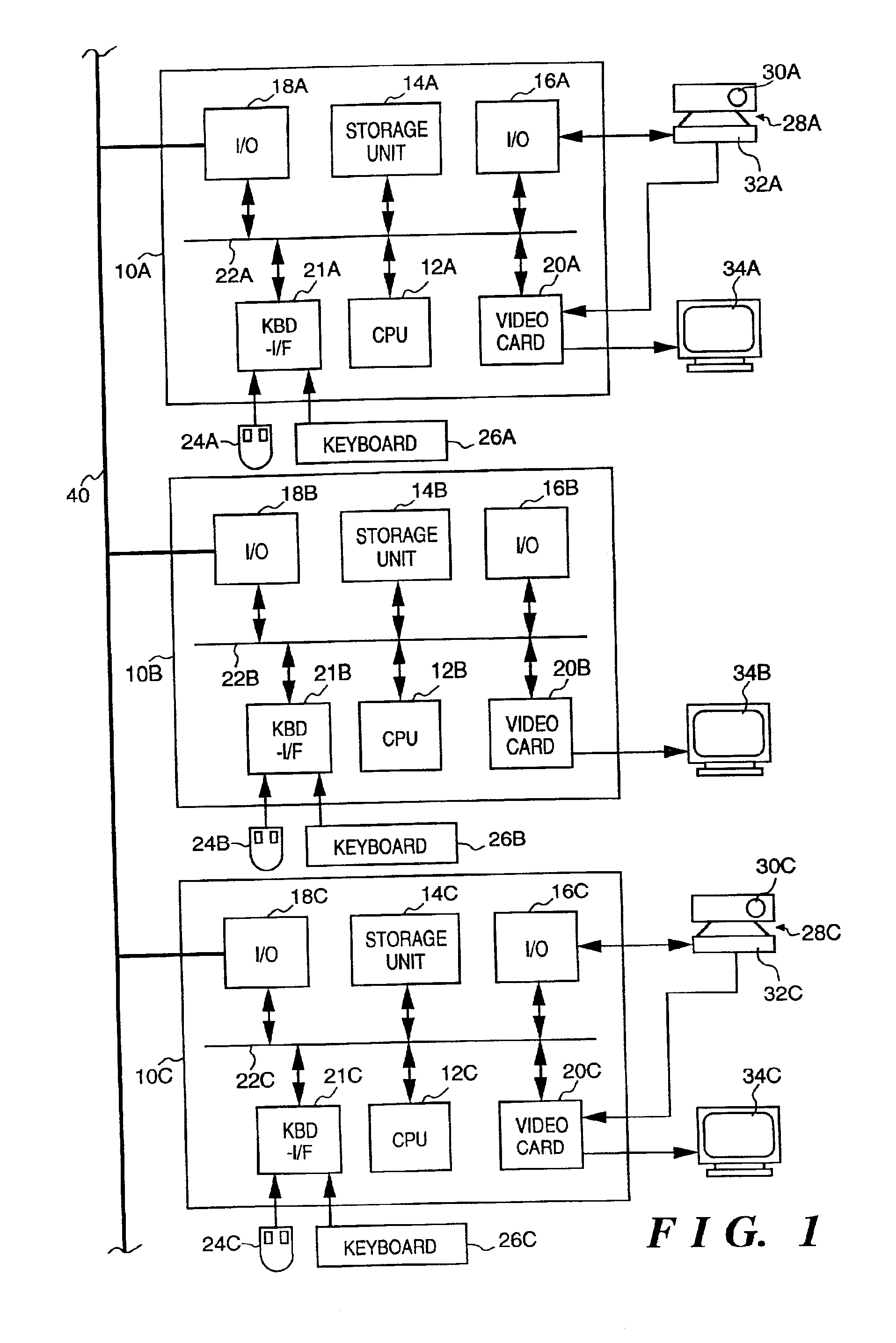
[0071]FIG. 1 is a block diagram showing an outline of the configuration of the first embodiment of the present invention. In the embodiment shown in FIG. 1, three workstations 10A, 10B, and 10C are connected to a network 40. These workstations 10A, 10B, and 10C include CPUs 12A, 12B, and 12C, storage units 14A, 14B, and 14C each having a ROM, a RAM, and a hard disk drive (external storage device), I / O ports 16A, 16B, and 16C, and 18A, 18B, and 18C, as input / output units, and video cards 20A, 20B, and 20C, all of which are connected to buses 22A, 22B, and 22C, respectively. Mouses 24A, 24B, and 24C, as pointing devices, and keyboards 26A, 26B, and 26C are also connected to the buses 22A, 22B, and 22C via keyboard interfaces (KBD-I / F) 21A, 21B, and 21C, respectively.

[0072]Camera apparatuses 28A and 28C whose panning, tilting, and zooming can be externally controlled are connected to the workstations 10A and 10C via the I / O ports 16A and 16C, respectively. These...

second embodiment

[Hardware Configuration]

[0124]FIG. 19 is a block diagram showing an outline of the configuration of a video communication apparatus as a basic element in the second embodiment of the present invention, i.e., a computer system to which cameras and microphones are connected. One or more computers having the configuration shown in FIG. 19 and one or more computers having a similar configuration are interconnected via a computer network.

[0125]In FIG. 19, reference numerals 210-1, 210-2, 210-3, . . . , denote video cameras; 212-1, 212-2, 212-3, . . . , microphones essentially attached to the video cameras 210; and 214-1, 214-2, 214-3, . . . , controllers which directly control panning, tilting, zooming, focus adjustment, and aperture of the video cameras 210 and audio inputs from the microphones 212-1, 212-2, 212-3, . . . , in accordance with external control signals. A selector 216 selects a video camera 210 (and a microphone 212) to be controlled and thereby selects output signals (vid...


PUM


Abstract

When an access request (a request for transfer of video and audio information or a request for a camera operation) to a camera apparatus connected to a network via a terminal is issued via the network, a camera management server processes the access request on the basis of an access right set by a user (or a manager) using the terminal to which the camera apparatus is connected. That is, the camera management server refers to an access right set file and grants or denies permission to access for the user whose has issued the access request. The user to whom the access permission is granted requests a camera control server to permit a camera operation via a camera control client and thereby can receive an image taken by the camera apparatus and voices collected by the camera apparatus and can perform panning, tilting, and zooming of the camera apparatus. Accordingly, to protect the privacy of a user using a terminal to which a camera apparatus is connected, it is possible to realize fine setting meeting the demand of the user at all times. Also, in a location where a camera apparatus connected to a network is installed, it is possible to prevent a leak of confidential information through the camera apparatus.

Description

[0001]This is a continuation of prior application Ser. No. 08 / 607,687, filed Feb. 26, 1996 now abandoned, to which priority under 35 U.S.C. §120 is claimed.BACKGROUND OF THE INVENTION[0002]1. Field of the Invention[0003]The present invention relates to a remote control system and an access control method for an information input apparatus and, more particularly, to a remote control system and a remote control method of remotely operating a camera apparatus equipped with a video camera and a microphone for a TV conference, and an access control method of controlling access to a camera apparatus connected to a network.[0004]2. Description of the Related Art[0005]As a monitoring system or a communication conference system, a network system has been proposed in which computers connected to video cameras are connected in a network to allow an operator to remotely operate a video camera connected to another arbitrary computer and to receive an image from a given video camera. In this vide...

Claims


Application Information

Patent Timeline
Patent Type & Authority Patents(United States)
IPC IPC(8): H04N5/232H04N7/18
CPCH04L63/101H04N7/181H04N5/23206H04N5/232H04N23/661H04N23/695
Inventor OKAZAKI, HIROSHISATO, HIROAKIKAWAI, TOMOAKIOYA, TAKASHIURISAKA, SHINYA
Owner CANON KK
Why Eureka
Try Eureka