
3D computer model processing apparatus

Inactive Publication Date: 2006-07-18
CANON EURPOPA NV
View PDF10 Cites 26 Cited by
  • Summary
  • Abstract
  • Description
  • Claims
  • Application Information

AI Technical Summary

Benefits of technology

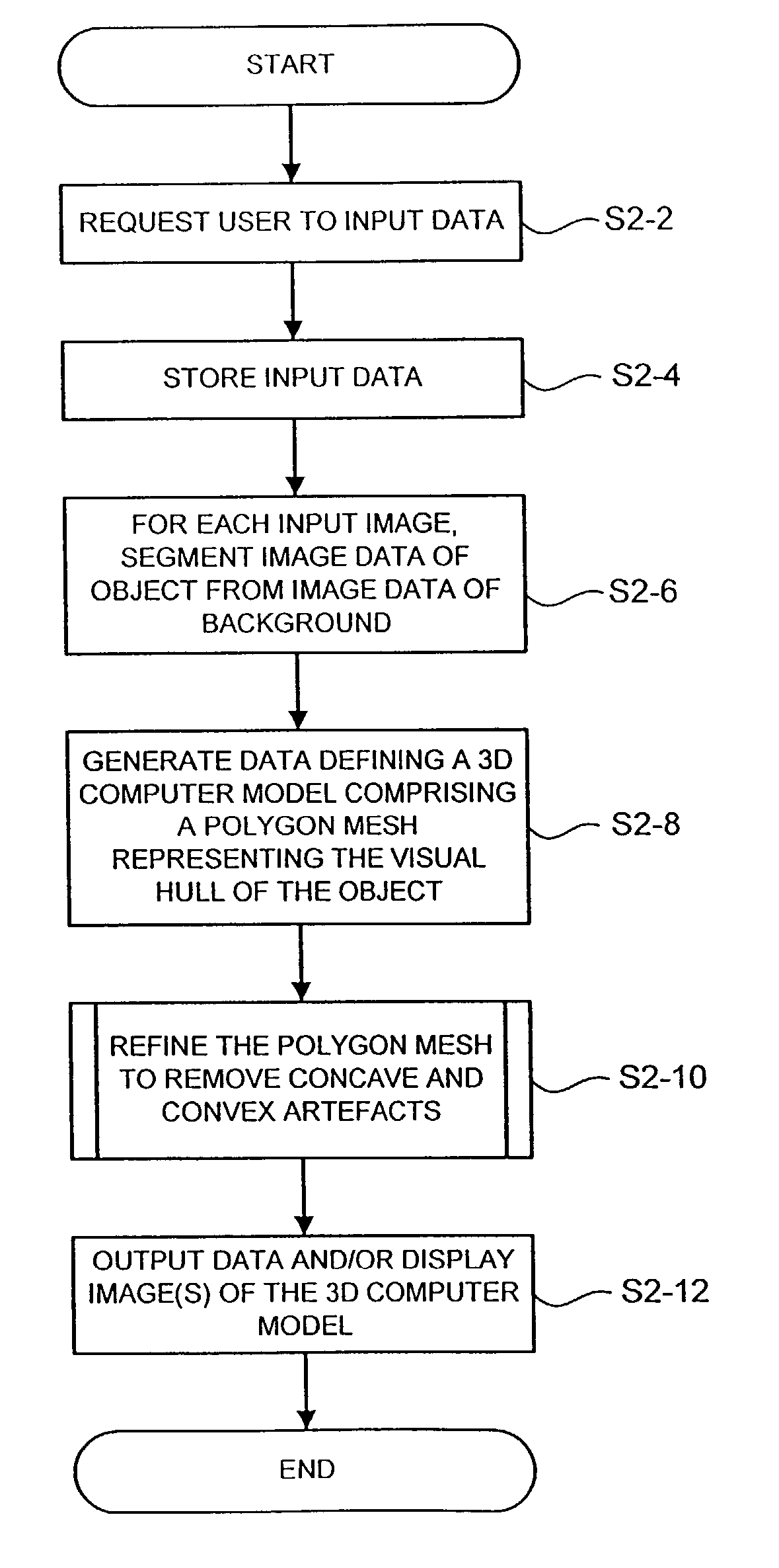
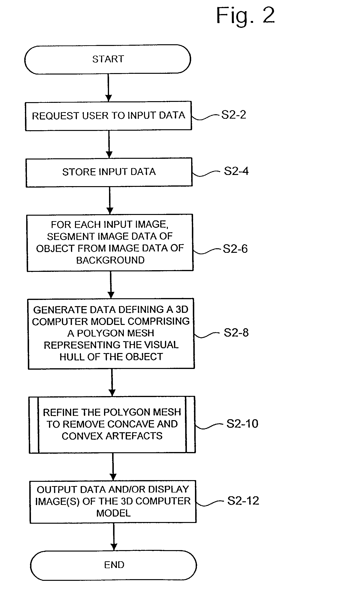
[0011]According to the present invention, there is provided a computer processing method and apparatus for processing data defining a polygon mesh representing the visual hull of an object, to remove artefacts in the computer model. At least one polygon in the mesh is changed, and the resulting change to the polygon mesh is tested against a reference silhouette in each image to determine whether it is consistent to within a predetermined tolerance with all of the reference silhouettes. A change which is consistent with all of the reference silhouettes is allowed in the computer model (or a corresponding change producing the same effect is allowed), but a change which is inconsistent with at least one reference silhouette is rejected. The process of making a change and testing it against the reference silhouettes is repeated a number of times.

Problems solved by technology

On the other hand, parts of the polygon mesh representing features actually present on the object are not changed because such a change causes the polygon mesh to become inconsistent with at least one reference silhouette, and therefore such a change is rejected.

Method used


Image

  • 3D computer model processing apparatus
  • 3D computer model processing apparatus
  • 3D computer model processing apparatus

Examples


first embodiment

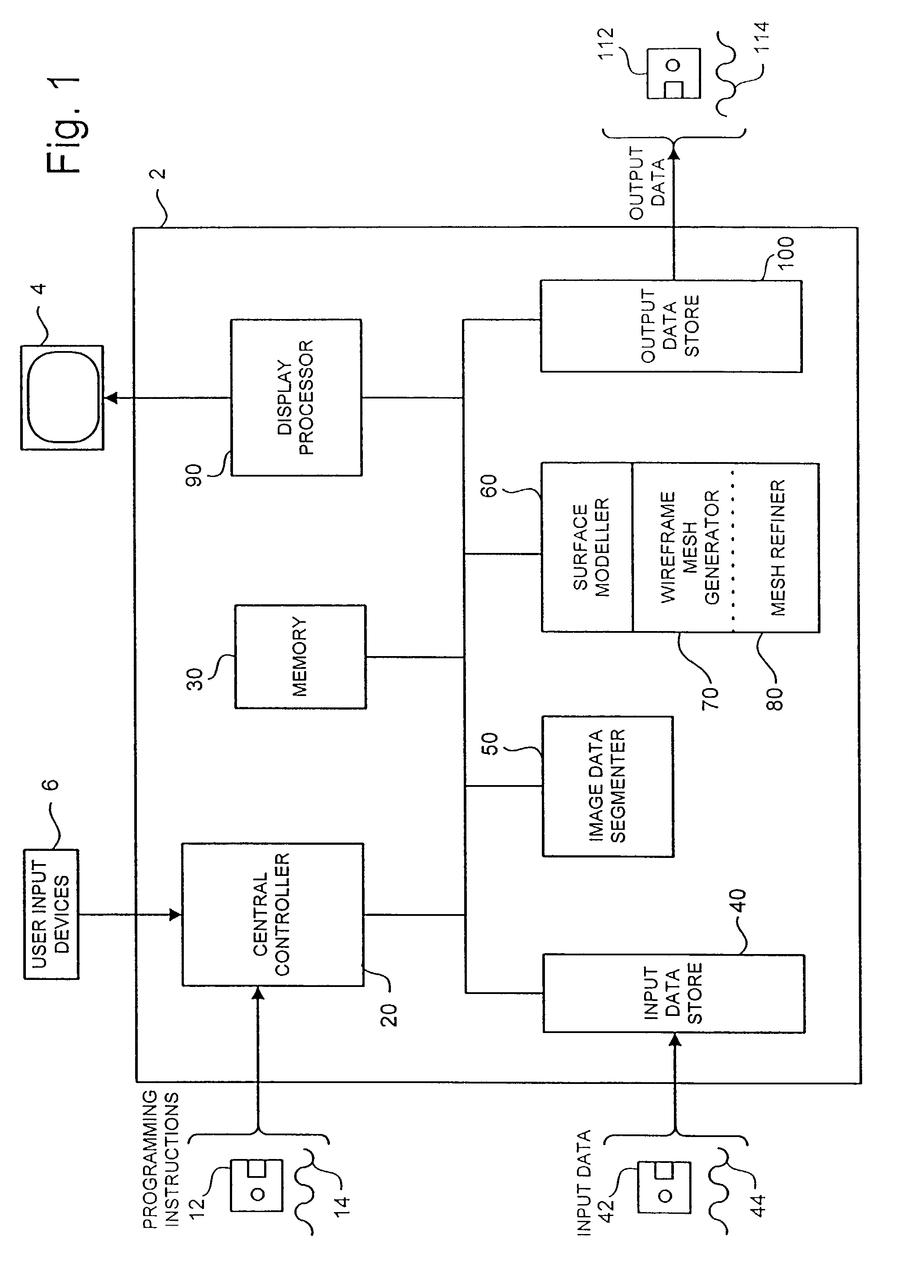
[0024]Referring to FIG. 1, an embodiment of the invention comprises a processing apparatus 2, such as a personal computer, containing, in a conventional manner, one or more processors, memories, graphics cards etc, together with a display device 4, such as a conventional personal computer monitor, and user input devices 6, such as a keyboard, mouse etc.

[0025]The processing apparatus 2 is programmed to operate in accordance with programming instructions input, for example, as data stored on a data storage medium, such as disk 12, and / or as a signal 14 input to the processing apparatus 2, for example from a remote database, by transmission over a communication network (not shown) such as the Internet or by transmission through the atmosphere, and / or entered by a user via a user input device 6 such as a keyboard.

[0026]As will be described in more detail below, the programming instructions comprise instructions to cause the processing apparatus 2 to become configured to process input da...

second embodiment

[0089]In the first embodiment described above, the processing performed by mesh refiner 80 at step S2-10 to refine the polygon mesh to remove concave and convex artefacts comprises decimation processing to remove edges in the polygon mesh without affecting the resulting polygon mesh's consistency with the silhouettes of the subject object.

[0090]However, mesh refiner 80 may be arranged to perform other types of processing at step S2-10 to refine the polygon mesh to remove concave and convex artefacts.

[0091]For example, a second embodiment will now be described in which mesh refiner 80 performs processing to smooth the polygon mesh without affecting the resulting mesh's consistency with the silhouettes of the subject object.

[0092]The components of the second embodiment and the processing operations performed thereby are the same as those in the first embodiment, with the exception of the processing performed by mesh refiner 80 at step S2-10 in FIG. 2. Accordingly, only the processing ...


PUM


Abstract

In a computer processing apparatus 2, a 3D computer model comprising a polygon mesh 500 representing the visual hull of an object 300 is generated by processing images of the object recorded at different positions and orientations to back-project the silhouette of the object in each image to give a respective cone which constrains the volume of 3D space occupied by the object. To remove concave and convex artefacts 510 in the polygon mesh 500, the polygon mesh is projected into each image to give a respective reference silhouette for each image. A change is made to at least one edge or vertex in the polygon mesh to give a refined polygon mesh, which is then projected into each image. The resulting silhouette in each image is tested against the corresponding reference silhouette. If the silhouette of the refined polygon mesh is the same as each reference silhouette, to within an allowable tolerance, then the changed edge or vertex is allowed in the polygon mesh, otherwise the polygon mesh is returned to its previous state. This processing to change and test the polygon mesh is carried out a number of times. Artefacts are removed from the polygon mesh because their removal does not make the polygon mesh inconsistent with the reference silhouettes. Parts of the polygon mesh representing actual features of the object are not changed because such a change causes the polygon mesh to become inconsistent with at least one reference silhouette and therefore such a change is rejected.

Description

BACKGROUND OF THE INVENTION[0001]1. Field of the Invention[0002]The present invention relates to computer processing of data defining a three-dimensional (3D) computer model of an object.[0003]2. Related Background Art[0004]Many methods are known for generating a 3D computer model of an object.[0005]The known methods include “shape-from-silhouette” methods, which generate a 3D computer model by processing images of an object recorded at known positions and orientations to back project the silhouette of the object in each image to give a respective endless cone containing the object and having its appex at the position of the focal point of the camera when the image was recorded. Each cone therefore constrains the volume of 3D space occupied by the object, and the intersection of the cones, which approximates the object and is known as the “visual hull” of the object, is calculated.[0006]Examples of shape-from-silhouette methods are described, for example, in “Looking to build a mode...

Claims


Application Information

Patent Timeline
Patent Type & Authority Patents(United States)
IPC IPC(8): G06K9/00G06T17/20
CPCG06T17/205G06T17/20
Inventor BAUMBERG, ADAM MICHAEL
Owner CANON EURPOPA NV
Learn More