Image-effect method and image interpolation method

a technology of interpolation and image, applied in the field of digital image effect and interpolation techniques, can solve the problems that the barrier between broadcasting and communication has been quickly beginning to disappear, and achieve the effect of high data compression and improved quality

Inactive Publication Date: 2006-07-18
JBF PARTNERS
View PDF8 Cites 5 Cited by
  • Summary
  • Abstract
  • Description
  • Claims
  • Application Information

AI Technical Summary

Benefits of technology

[0006]Conventionally, various image effects have been proposed and used. For example, there are walk-through, multi-viewpoint image, special filtering, pseudo stereoscopic vision and so forth. As the use of and importance of images increases in society in the future, it is important that these image effects be provided with further improved quality and they can be implemented with high data compression to meet the requirements of communications and transmission systems. The present invention has been made in view of these circumstances, and an object of the invention is to provide an image effect technique by which motion pictures can be generated based on a small amount of image data.
[0012]The above-mentioned matching method utilizing the critical points is an application of the technique (referred to as the “base technology” hereinafter) proposed in Japanese Patent No. 2927350 owned by the same assignee of the present patent application, and the method is also suitable for the detection of the corresponding points. However, it is to be noted that the base technology is not prerequisite for the present invention and that the base technology does not touch on the features of the present invention relating to the lattice points or the polygons determined thereby. Introduction of a somewhat simplified technique, such as the polygons in the embodiments of the present invention, makes possible a significant reduction in the size of the corresponding point file.
[0014]Further, since the first and second images and the corresponding point file can be used to generate intermediate images through interpolation computation, the present invention realizes what is called morphing in image effects. Also, if the first and second images are considered as frames in a motion picture, the present invention can be recognized as a compression technique for motion pictures. Storage of the first and second images and the corresponding point file for use in generating intermediate images can achieve reproduction of motion pictures, and thereby significant improvements can be achieved in the transmission, storage and so forth of motion pictures.
[0021]The image-effect function may include sequentially choosing two images out of a plurality of images as the first and second images, and smoothly and continuously displaying the intermediate image or images generated from the sequentially chosen two images. For example, when many discrete images with different viewpoints are sequentially interpolated and the intermediate images are generated, a panoramic image or image sequence can be obtained. If the intermediate images are displayed in order as if the viewpoint is moving over time, a “walk-through” image can be obtained. The image-effect function may also include displaying an intermediate image obtained by interpolating an image to be processed in two directions.
[0024]In a particular case, the intermediate image may be generated through a streaming process for either the first image or the second image and the correspondence information. In this case, memory capacity required for the process can be reduced and it is advantageous for implementation to portable telephones or other wireless or mobile terminals.

Problems solved by technology

Thus, a barrier that had previously existed between broadcasting and communications is quickly beginning to disappear.

Method used


Image

  • Image-effect method and image interpolation method
  • Image-effect method and image interpolation method
  • Image-effect method and image interpolation method

Examples


embodiment 1

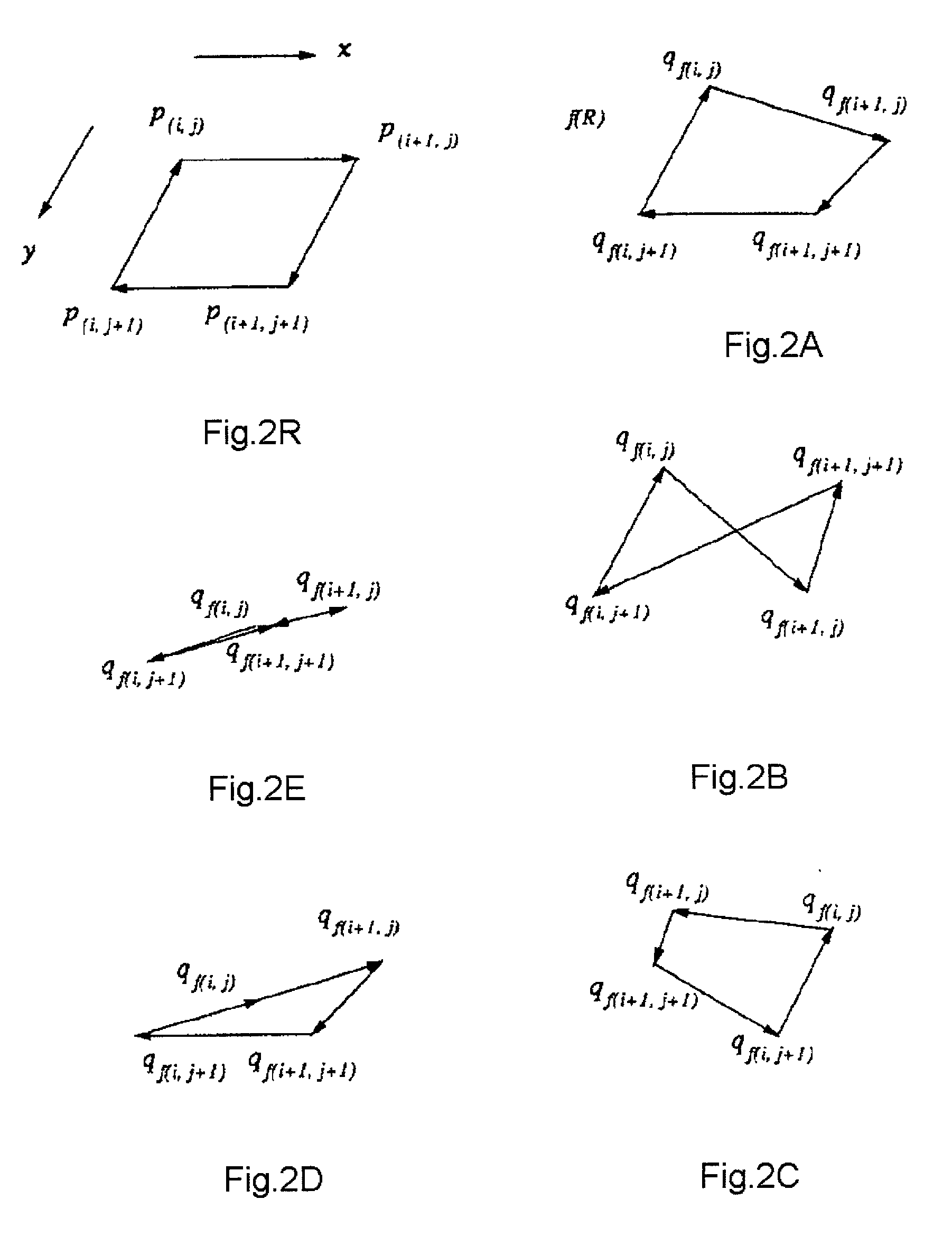
[0297]FIG. 18 shows a first image I1 and a second image I2, where certain pixels p1(x1, Y1) and P2(x2, Y2) correspond therebetween. The correspondence of these pixels may be obtained using the base technology.

[0298]Referring to FIG. 19, when a mesh is provided on the first image I1, a corresponding polygon mesh can be generated on the second image I2. Now, a polygon R1 of interest on the first image I1 is determined by four lattice points A, B, C and D. Let this polygon R1 be called a “source polygon.” As has been shown in FIG. 18, these lattice points A, B, C and D have respectively corresponding points A′, B′, C′ and D′ on the second image I2, and a polygon R2 formed thus by the corresponding points is called a “destination polygon.” In a particular case, the source polygon may be a rectangle while the destination polygon may be a quadrilateral. In the base technology a correspondence relation between images is described pixel-by-pixel, however, according to this embodiment, the c...

embodiment 2

[0310]The image-effect apparatus described in the first embodiment can be utilized for commodity presentation in electronic commerce. The apparatus according to the second embodiment (hereinafter referred to as “a commodity showing apparatus”) uses two adjacent images (i.e. photographs or the like) of a commodity taken from different angles as the first image I1 and the second image I2, and smoothly interpolates between these images so as to display the commodity to a user. In particular, if photographs taken from different angles of every 10 degrees around the commodity are interpolated sequentially, a smooth 360-degree revolving image can be obtained. Conventionally, such a smooth revolving image of the commodity would require the photographs to be taken from different angles of every 1 or 2 degrees, however, when the technique described in the first embodiment is utilized, the difference of the angles can be as much as 10 to 20 degrees.

[0311]Differing from the first embodiment, t...

embodiment 3

[0320]The generation of intermediate images provides opportunities for various image-effect functions. Although image effects are mentioned as a generalization above, the following provides further details on image effects. Some examples of such image-effect functions are as follows.

[0321]Two adjacent images out of a plurality of related images are chosen as the first and second images, and an intermediate image or images between these images are generated and displayed. Thereafter, other adjacent images, taken in order, are chosen as the first and second images and an intermediate image or images therebetween is generated. For example, using images S, T, U whose viewpoints are slightly different, intermediate images between the images S and T are first generated and intermediate images between the images T and U are next generated so that a sequence of images can be continuously displayed. Namely, when many discrete images with different viewpoints are sequentially interpolated and...


PUM


Abstract

An image input unit acquires a first image and a second image. A matching processor computes a pixel matching between the images so that corresponding points are obtained on the second image with respect to lattice points of a mesh defined on the first image. A result thereof is recorded as a corresponding point file. An intermediate image generator generates an intermediate image of the first image and the second image based on the corresponding point file. Since the corresponding point file is composed of corresponding lattice points alone rather than corresponding pixels or the like, the amount of data is relatively small, and thereby allows efficient implementation of and application to various image effects, motion picture compression, on-line commodity presentation, and mobile applications.

Description

BACKGROUND OF THE INVENTION[0001]1. Field of the Invention[0002]The present invention relates to image processing techniques, and more particularly relates to a method and apparatus for digital image-effect and interpolation techniques.[0003]2. Description of the Related Art[0004]As a part of the digital revolution, many users have come to enjoy services on the Internet from personal computers and portable telephones. The digital revolution is now spreading to broadcast services and movies, including digital satellite broadcasts. Thus, a barrier that had previously existed between broadcasting and communications is quickly beginning to disappear. Moreover, as broadband communications grow, multimedia content and culture will experience significant development, and, as a part of this multimedia culture, the distribution of video or motion pictures will become a key technology.[0005]When humans acquire information from the outside world, images are capable of conveying much more infor...

Claims


Application Information

Patent Timeline
Patent Type & Authority Patents(United States)
IPC IPC(8): G06K9/32G06K9/46G06K9/64G06T9/00H04N7/26
CPCG06K9/4609H04N19/54G06K9/6206G06V10/443G06V10/754
Inventor NAGASHIMA, HIROKIAKIYOSHI, KOZOAKIYOSHI, NOBUO
Owner JBF PARTNERS
Why Eureka
Try Eureka