Paperless tablet automation apparatus and method

a technology of automation apparatus and tablet, which is applied in the direction of total factory control, programme control, instruments, etc., can solve the problems of paper system nature susceptible to information loss, information recorded in disparate documents, information can be misplaced or incorrectly transcribed,

Inactive Publication Date: 2006-07-18
RAPP III ROY W
View PDF27 Cites 9 Cited by
  • Summary
  • Abstract
  • Description
  • Claims
  • Application Information

AI Technical Summary

Benefits of technology

[0010]The factory floor tablet automation system can also include a statistical process control (SPC) parameter setup station having a processor unit, a display device, and an input device. The SPC station communicates with the server computer. The SPC station enables a user to add an SPC data entry point by positioning an SPC icon for the SPC data entry point on a sketch associated with an job and associating a quality characteristic of the job with the SPC data entry point. A portable tablet device displays the SPC icon for the SPC data entry point when the sketch is displayed on the portable tablet device. The operator can enter SPC data for the quality characteristic of the SPC job by selecting the SPC icon of the SPC data entry point on the portable tablet device.

Problems solved by technology

Additionally, the nature of the paper system is susceptible to lost information, incorrect information, and information recorded in disparate documents which are not readily available to the person needing the information.
Papers can be misplaced or information transcribed incorrectly.
Paper systems also significantly delay responses to customer inquires because the manager must determine who is working on the job, either seek out that person or check a job board for status and sometimes determine additional information, such as why a job is suspended.

Method used


Image

  • Paperless tablet automation apparatus and method
  • Paperless tablet automation apparatus and method
  • Paperless tablet automation apparatus and method

Examples


Embodiment Construction

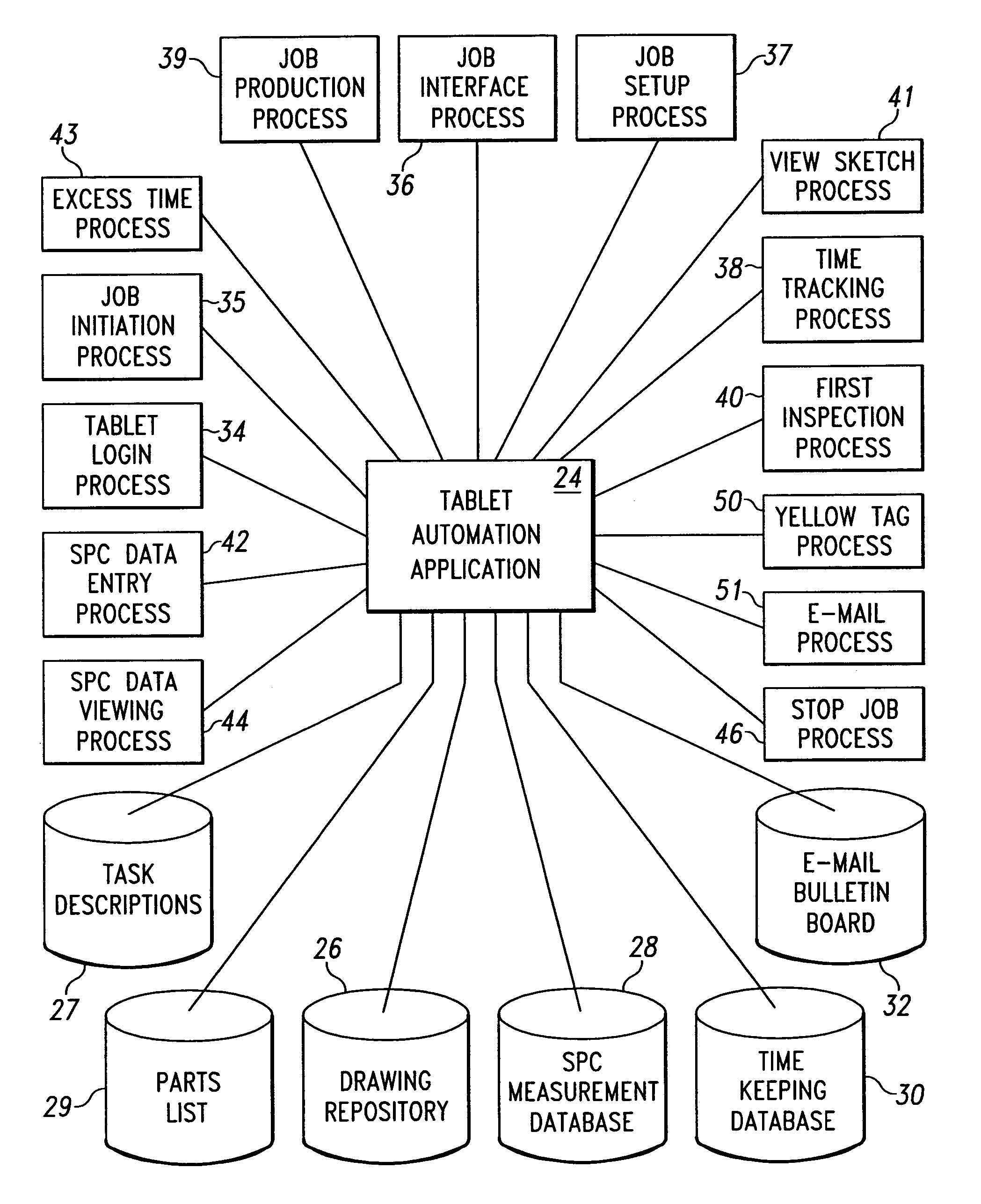
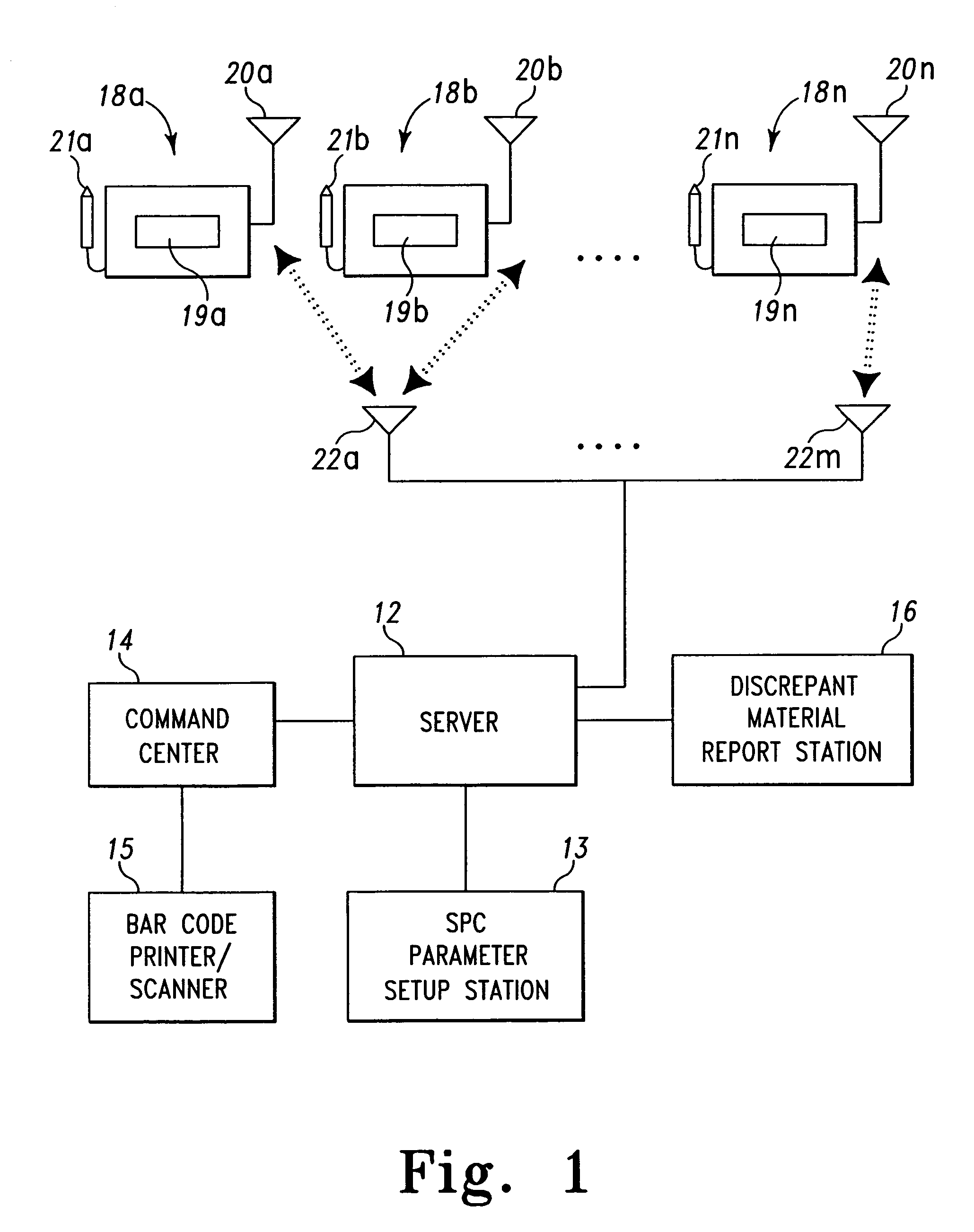
[0068]A block diagram of a factory floor tablet automation system 10 is shown in FIG. 1. The tablet automation system 10 includes a server computer 12, a command center 14, a plurality of portable tablet computer units 18a–18n, and a plurality of transceivers 22a–22m which are part of a Radio Frequency Local Area Network (RF LAN). Each tablet unit 18a–18n includes an antenna 20a–20n. The server 12 is connected to the transceivers 22a–22m which are distributed throughout the factory. The tablet units 18a–18n communicate with the server 12 through transceivers 22a–22m.

[0069]A tablet unit 18 includes a central processor, memory, a display screen 19 and an operator input device, such as a stylus 21 as shown in FIG. 1. It has been found that a VADEM PC Companion Model C-100 with RF antenna and stylus peripherals works well in this application.

[0070]The command center 14 is used to create identifiers for operators and manufacturing orders and to assign operators to tasks. FIG. 1 shows a ...


PUM


Abstract

A factory floor tablet automation system enables the storing, collecting and processing manufacturing data generated at one or more facilities during manufacturing, and making manufacturing data accessible from the one or more facilities. A local processor is located at each facility, and a plurality of portable tablet devices are located in each facility. One or more transceivers located throughout each facility, each transceiver being connected to the local processor in each facility. The plurality of portable tablet devices is in wireless communication with the local processor through the transceivers and the tablet antennas. A server computer having a processor unit and storage device is connected to local processors through a network.

Description

CROSS-REFERENCE TO RELATED APPLICATIONS[0001]This is a divisional of U.S. patent application Ser. No. 09 / 724,115, filed Nov. 28, 2000 now abandoned, which is a continuation-in-part of U.S. patent application Ser. No. 09 / 478,251, filed Jan. 6, 2000, now U.S. Pat. No. 6,400,997, the disclosures of which are expressly incorporated herein by reference.FIELD OF THE INVENTION[0002]The present invention is related to apparatus and methods for factory automation and tracking. In particular, the present invention is directed to a factory automation apparatus which includes a plurality of portable tablets and an automation server in wireless communication, and the software for implementing a paperless factory automation system with that apparatus.BACKGROUND OF THE INVENTION[0003]Facilities which machine custom parts are traditionally managed with a variety of paper systems. For example, time records are kept on time cards which need to be gathered and analyzed. Component drawings for a given ...

Claims


Application Information

Patent Timeline
Patent Type & Authority Patents(United States)
IPC IPC(8): G06F19/00G06F11/34G07C1/10G05B19/418
CPCG05B19/4183G05B19/4185G06Q10/063114G05B2219/36159G05B2219/31289Y02P90/02
Inventor RAPP, III, ROY W.
Owner RAPP III ROY W
Why Eureka
Try Eureka