Vision-based obstacle avoidance

a technology of obstacle avoidance and vision, applied in the direction of manufacturing tools, process and machine control, instruments, etc., can solve the problems of limited sensor range and vehicle power requirements, see obstacles, and limited sensor rang

Inactive Publication Date: 2006-07-18
LOS ALAMOS NATIONAL SECURITY
View PDF5 Cites 13 Cited by
  • Summary
  • Abstract
  • Description
  • Claims
  • Application Information

AI Technical Summary

Benefits of technology

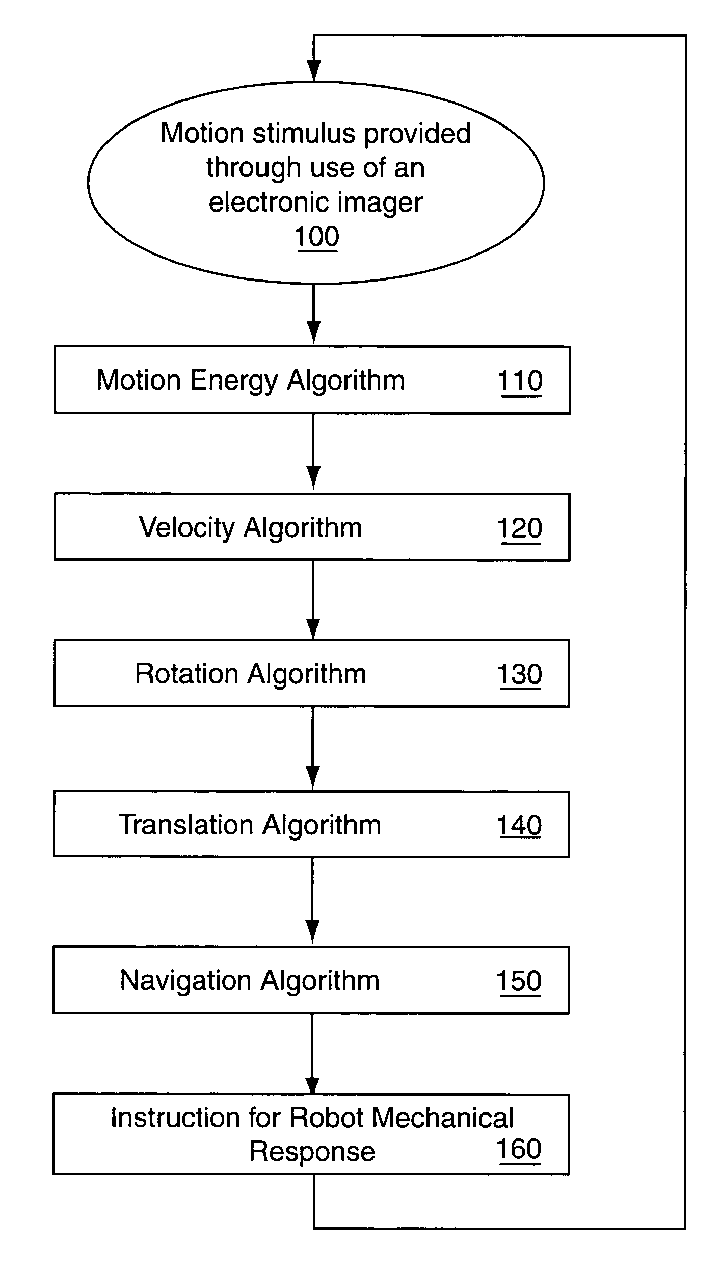
[0014]In accordance with the purposes of the present invention, as embodied and broadly described herein, the present invention includes a method for allowing a robot to avoid objects along a programmed path. First, a field of view for an electronic imager of the robot is established along ...

Problems solved by technology

Those technologies also radiate power, resulting in fundamental limitations on sensor range and vehicle power requirements.
Unlike vision, it also works in the dark, but can only see obstacles that radiate heat.
Sensor range is limited only by the scene and environmental factors, an...

Method used


Image

  • Vision-based obstacle avoidance
  • Vision-based obstacle avoidance
  • Vision-based obstacle avoidance

Examples


example

Hardware Design Features

[0068]Referring to FIG. 4, in order to practice the method of the present invention, a hardware system comprising the following physical components was assembled: remote control robotic chassis 200, electronic imaging device 210, video transmitter 220, video receiver 230, digital multiprocessor computer 240, control radio transmitter 250, and control radio receiver 260.

[0069]Robotic chassis 200 was a small remote control model tank, just large enough to support the required payload of a few pounds. The model tank's control system, supplied with the model, included two drive motors, radio receiver 260 of a type used by model airplanes, an electronic circuit to convert servo commands received from receiver 260 into motor control signals, and two rechargeable batteries that powered receiver 260 and the drive motors. The original tank model was stripped of its cosmetic accessories to make room for an aluminum platform upon which the custom image acquisition and v...


PUM


Abstract

A method for allowing a robot to avoid objects along a programmed path: first, a field of view for an electronic imager of the robot is established along a path where the electronic imager obtains the object location information within the field of view; second, a population coded control signal is then derived from the object location information and is transmitted to the robot; finally, the robot then responds to the control signal and avoids the detected object.

Description

RELATED APPLICATIONS[0001]This application claims the benefit of Provisional Application No. 60 / 424,596 filed on Nov. 7, 2002 for applicant John Galbraith.STATEMENT REGARDING FEDERAL RIGHTS[0002]This invention was made with government support under Contract No. W-7405-ENG-36 awarded by the U.S. Department of Energy. The government has certain rights in the invention.REFERENCE TO COMPUTER PROGRAM LISTING APPENDIX[0003]This application includes a computer program listing appendix submitted in duplicate on two compact discs, CD-R. The computer program listing for practicing the invention is incorporated herein in its entirety by reference. The following files reside on the compact discs:[0004]NameSizeDateAdelsonBergen.cc26,845 kb Oct. 8, 20022:40 PMCamera.cc9,151 kbMay 11, 20022:21 PMCollisionServer.cc4,913 kbOct. 10, 20023:46 PMElement.cc1,672 kbSep. 26, 200211:28 PMInitializer.cc8,474 kbOct. 9, 200212.42 PMMotionServer.cc8,878 kbOct. 10, 200212:09 PMMpegDecoder.cc1,674 kbApr. 15, 200...

Claims


Application Information

Patent Timeline
IPC IPC(8): G06F19/00B25J9/18G05D1/02G05D23/19
CPCG05D1/0246
Inventor GALBRAITH, JOHN
Owner LOS ALAMOS NATIONAL SECURITY
Why Eureka
Try Eureka