Point-to-point path planning

a path planner and point-to-point technology, applied in the field of path planners, can solve the problem of estimated economic cost of traversing each candidate path or a portion, and achieve the effect of lowest estimated economic cos

Inactive Publication Date: 2006-07-18
DEERE & CO
View PDF33 Cites 103 Cited by
  • Summary
  • Abstract
  • Description
  • Claims
  • Application Information

AI Technical Summary

Problems solved by technology

An economic cost is estimated for traversing each candidate path or a portion thereof between the starting point and the termination point.

Method used


Image

  • Point-to-point path planning
  • Point-to-point path planning
  • Point-to-point path planning

Examples


Embodiment Construction

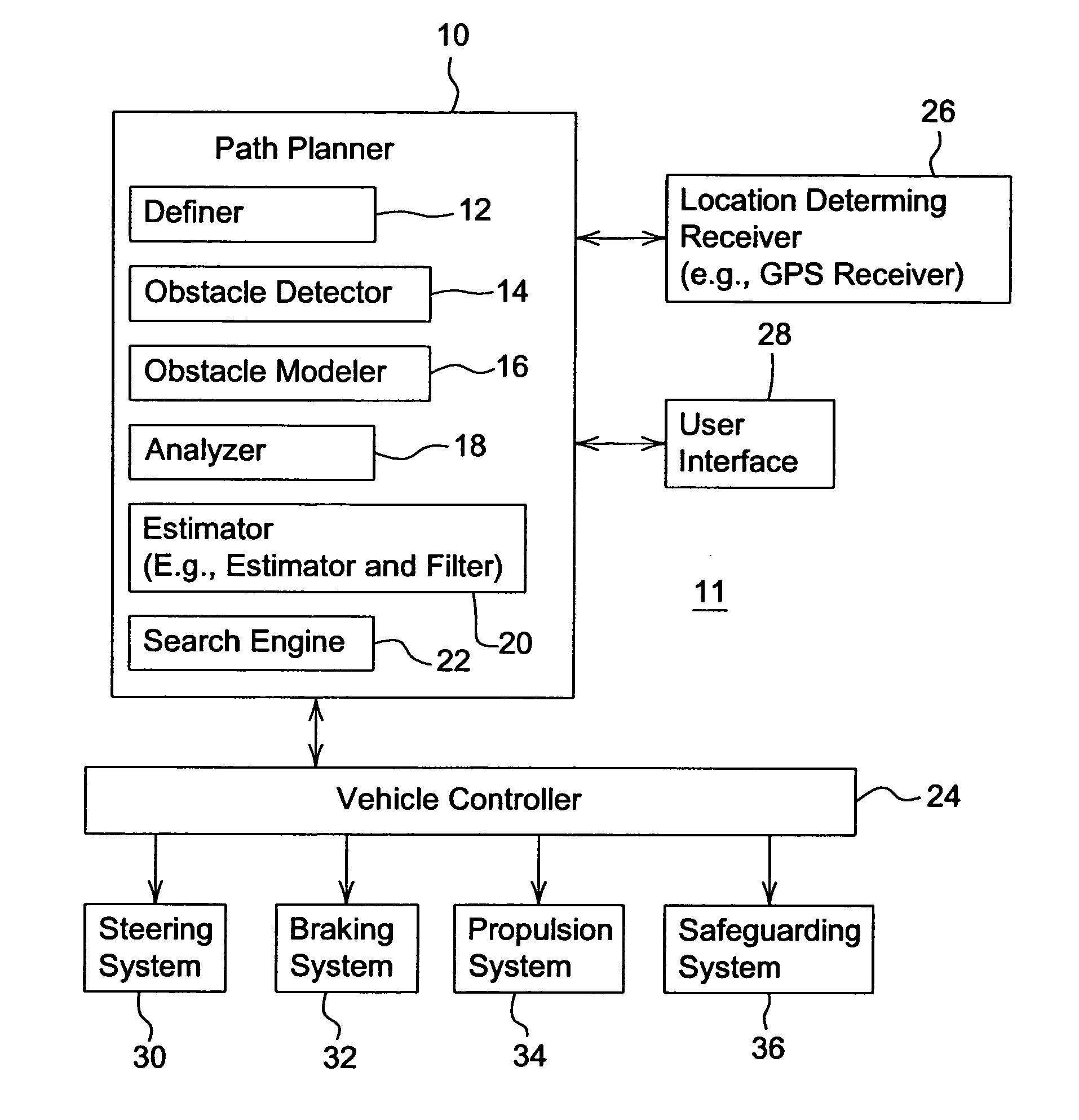
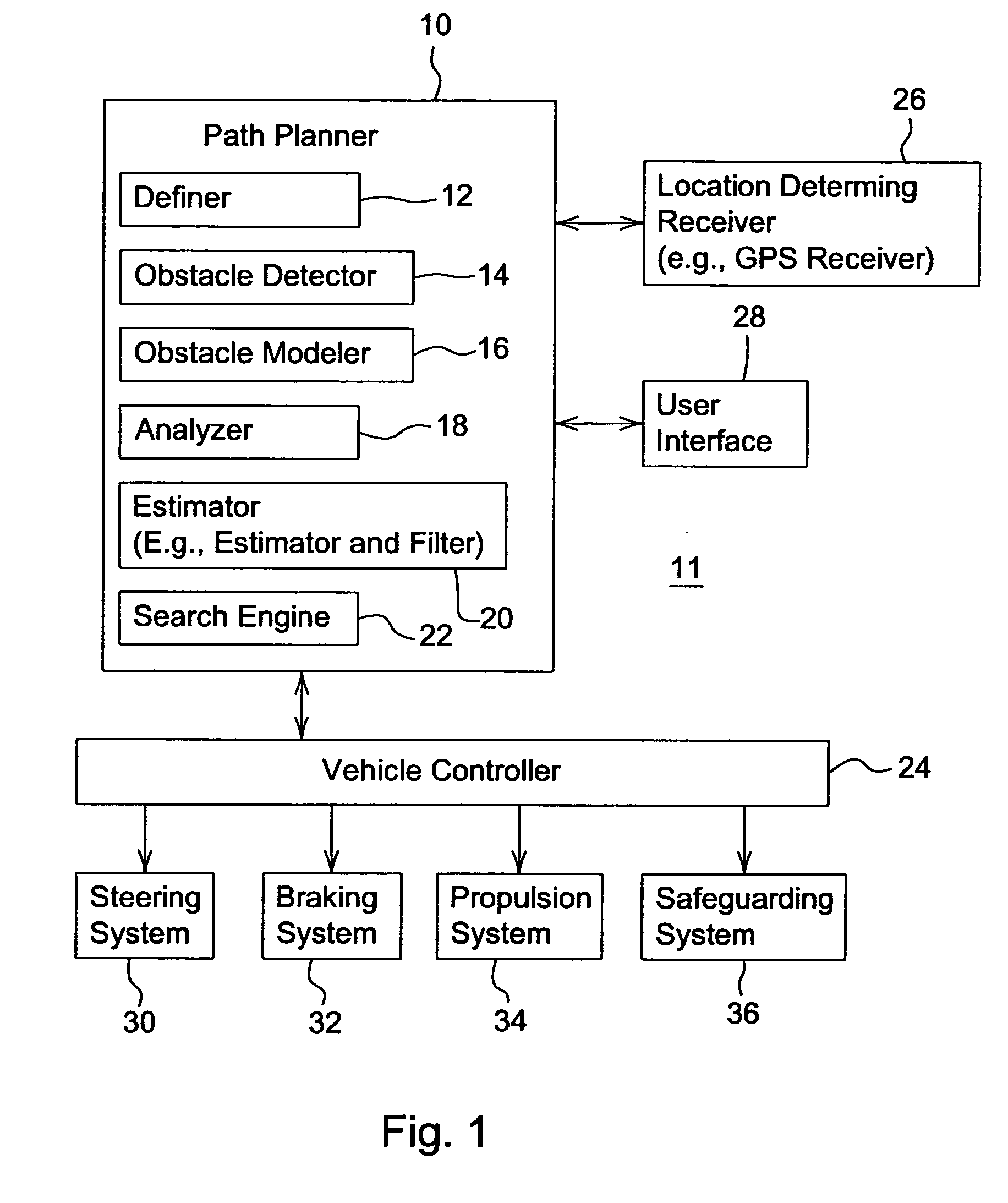
[0013]FIG. 1 is a block diagram of a path planning system 11. The path planning system 11 comprises a location-determining receiver 26 and a user interface 28 coupled to a path planner 10. The path planner 10 is coupled to a vehicular controller 24. In turn, the vehicular controller 24 is coupled to a steering system 30, a braking system 32 (if present), a propulsion system 34, and a safeguarding system 36.

[0014]The path planner 10 comprises a definer 12, an obstacle detector 14, an obstacle modeler 16, an analyzer 18, an estimator 20 and a search engine 22, which may be collectively referred to as the components of the path planner 10. The components (12, 14,16, 18, 20 and 22) of the path planner 10 may communicate with one another.

[0015]A location-determining receiver 26 may define a starting point for the vehicle, whereas the definer 12 defines a termination point for the vehicle. The starting point may comprise a starting point (e.g. two or three dimensional coordinates) and sta...


PUM


Abstract

A path planner and a method for determining a path for a vehicle comprises defining a starting point for the vehicle. A termination point is defined. An obstacle detector detects one or more obstacles in a work area between the starting point and the termination point. A boundary zone is defined about each corresponding obstacle. Candidate paths are identified between the starting point and the termination point. Each candidate path only intersects each boundary zone once for each corresponding obstacle. An economic cost is estimated for traversing each candidate path or a portion thereof between the starting point and the termination point. A preferential path is selected from the identified candidate paths based on the preferential path being associated with a lowest estimated economic cost.

Description

[0001]This application is a continuation-in-part of U.S. application Ser. No. 10 / 680,307, filed Oct. 7, 2003 and entitled, MODULAR PATH PLANNER.FIELD OF THE INVENTION[0002]This invention relates to a path planner and a method for planning a path from one point to another.BACKGROUND OF THE INVENTION[0003]A path planner may be used to determine one or more path plans for a vehicle to move over a work area from a first point to a second point, spaced apart from the first point. The work area may represent a field for growing a crop, a battlefield, or any other terrain. The work area may include one or more obstacles that may prevent, but need not prevent, a generally linear path from the first point to the second point. Accordingly, there is a need for a path planner and a method for applying path plan for the vehicle to navigate the work area.SUMMARY OF THE INVENTION[0004]A path planner and a method for determining a path for a vehicle comprises defining a starting point for the vehic...

Claims


Application Information

Patent Timeline
Patent Type & Authority Patents(United States)
IPC IPC(8): G01C21/34A01B69/04G01C21/00
CPCA01B69/008B60K6/48G01C21/00G01C21/20G05D1/0217G05D1/024G01C21/005B60W2510/244B60W2520/10B60W2550/402Y02T10/6221G05D2201/0201G05D2201/0209B60W2556/50Y02T10/62
Inventor FLANN, NICHOLAS SIMONHANSEN, SHANE LYNNGRAY, SARAH ANN
Owner DEERE & CO
Why Eureka
Try Eureka