Workpiece seat for bar-shaped workpieces

a workpiece and seat technology, applied in the field of workpiece seats, can solve the problems of occupying such space, elongating the workpiece seat, and complicated structural structure of the known fixing means

Inactive Publication Date: 2006-07-25
DECKEL MAHO PFRONTEN GMBH
View PDF7 Cites 2 Cited by
  • Summary
  • Abstract
  • Description
  • Claims
  • Application Information

AI Technical Summary

Benefits of technology

[0009]The present invention relates to a machine tool having an elongated housing, a spindle rotatably supported in the housing, and an electric direct drive for the spindle, the rotor of which is fixed on the spindle casing and the stator of which is fixed in the housing. Clamping means are provided at the working-side end of the spindle for fixedly clamping a bar-shaped workpiece. A connection unit provided at the rear part of the housing allows for energy supply and a means for releasably fixing the spindle in the housing.

Problems solved by technology

However, this known fixing means is structurally complicated and occupies such space that the workpiece seat is elongated.
Another technical disadvantage of this fixing means is that the spindle is only fixed at its rear end in the housing.
These contortions of the spindle ultimately lead to positioning errors of the workpiece when it is machined.

Method used


Image

  • Workpiece seat for bar-shaped workpieces
  • Workpiece seat for bar-shaped workpieces
  • Workpiece seat for bar-shaped workpieces

Examples


Embodiment Construction

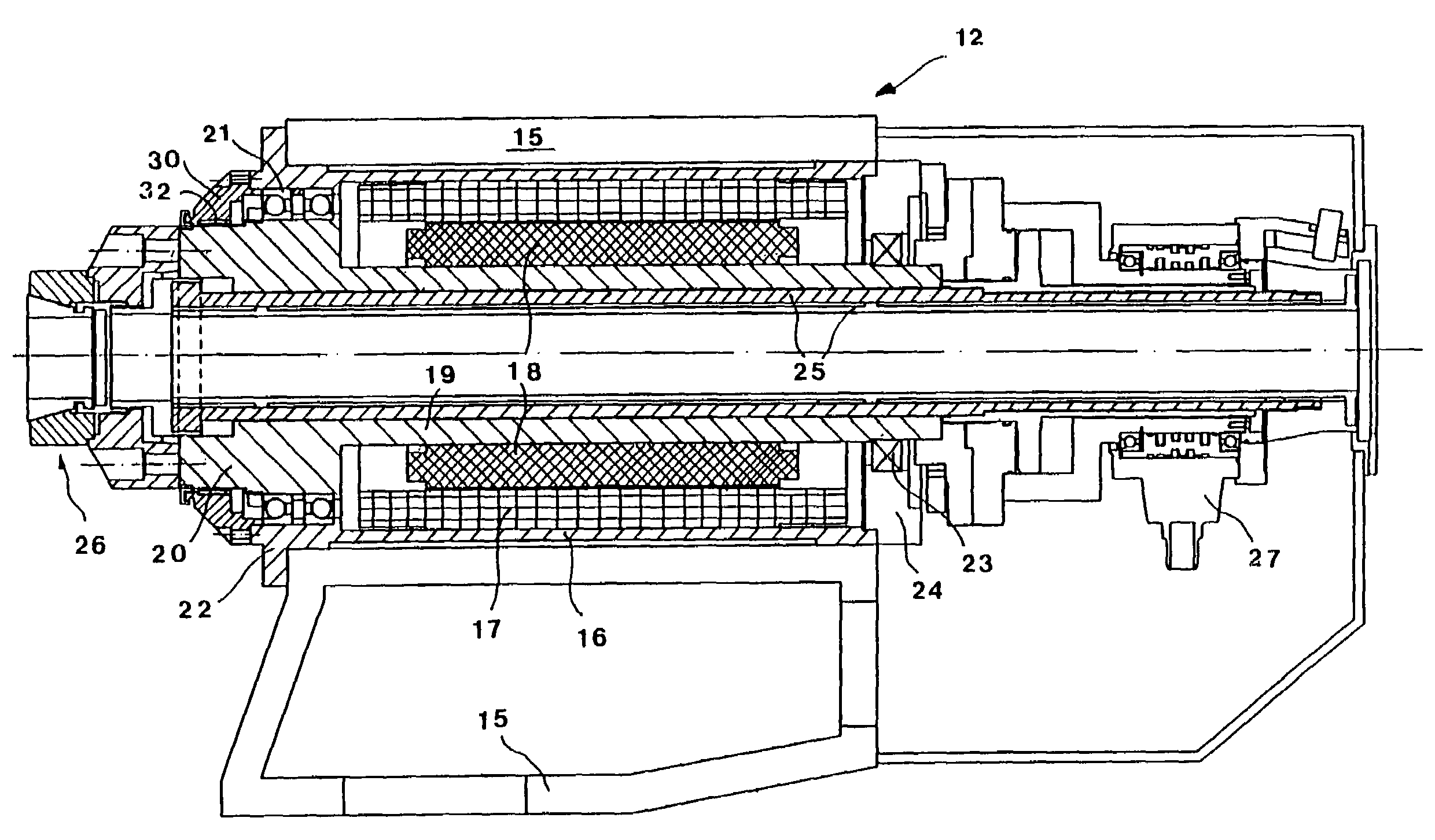
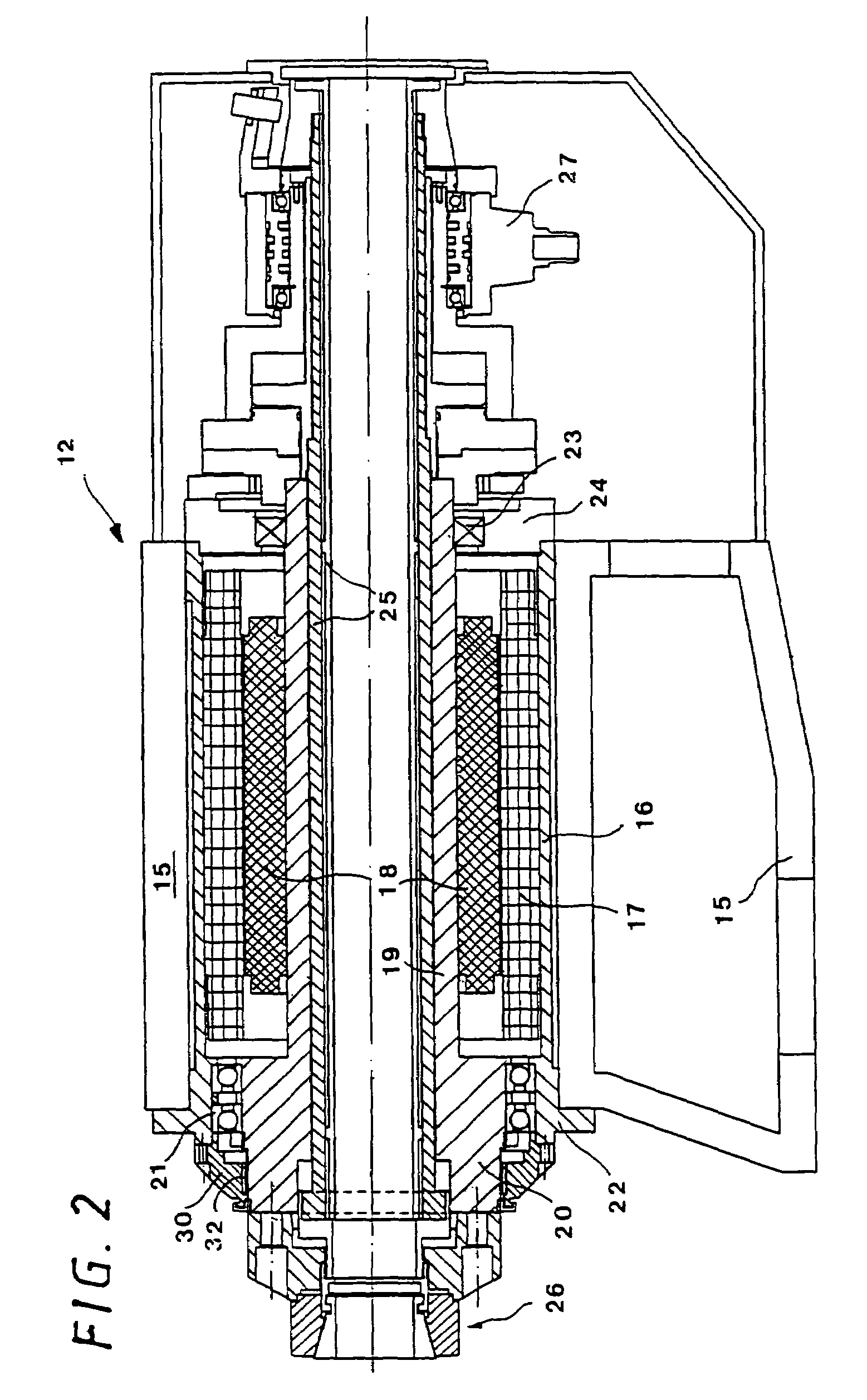
[0019]The basic structure of a workpiece seat according to the invention is shown in axial cross-section in FIG. 2. An electric direct drive is arranged coaxially in hollow-cylindrical elongated housing 16. The housing is surrounded by dimensionally stable and load-bearing cover element 15. Drive stator 17 is fixed at the inner wall of the housing and rotor 18 is fixed on the peripheral wall of elongated hollow-cylindrical spindle 19. Radially enlarged front part 20 of the spindle is supported in front-side ball bearings 21 in front end part 22 of the housing. The rear end part of the spindle is supported via bearing 23 in housing part 24. In the continuous cylindrical interior space of the spindle, sleeve arrangement 25 is located, which forms part of a clamping means for a bar-shaped workpiece inserted into the interior space. Clamping chuck 26, shown on the left side of FIG. 2, is associated to this clamping means. Clamping wedges fixedly clamp or release the front end of the wor...


PUM

PropertyMeasurementUnit
driving forceaaaaaaaaaa
diameteraaaaaaaaaa
forcesaaaaaaaaaa

Abstract

A workpiece seat for the machining of bar-shaped workpieces by milling and turning. The workpiece seat has an elongated housing, a spindle rotatably supported in the housing, and an electric direct drive for the spindle. The drive rotor is fixed on the spindle and the drive stator is fixed in the housing. Clamping means are provided at the working end in the spindle for fixing a bar-shaped workpiece in the spindle. A connection unit is provided at the rear part of the housing for power supply. A fixing means is provided for fixing the spindle in the housing. To achieve high machining accuracy of thick bars and high clamping forces at reduced longitudinal dimensions, as well as relatively simple design, the fixing means is formed as a compact part and is arranged at the working end of the housing.

Description

BACKGROUND OF THE INVENTION[0001]1. Field of the Invention[0002]The present invention relates generally to machine tools, and more specifically to a workpiece seat for the machining of bar-shaped workpieces by milling and turning.[0003]2. Discussion of Related Art[0004]Various types of machine tools have been developed for the machining of workpieces in a single chucking by drilling and milling, as well as turning. This operation provides several advantages. For example, it provides higher machining accuracy, higher throughput and reduced idle times because set-up operations become unnecessary. In general, two types of such machines have been in use. In the first, the workpieces are processed for the most part by turning. In the second, the workpieces are processed preferably by milling. This latter type is akin to milling machines.[0005]The machine tool shown in FIG. 1 belongs to the latter type. It has a relatively broad movable column 1 in bottom trough 2. Horizontal slides 3 are...

Claims


Application Information

Patent Timeline
Patent Type & Authority Patents(United States)
IPC IPC(8): B25B27/14B23B19/02B23Q1/00B23Q1/70B23Q5/10
CPCB23Q1/70B23Q5/10Y10T82/2562Y10T82/2521Y10T82/2518Y10T29/53935Y10T409/309352Y10T82/26Y10T29/5114Y10T82/2552
Inventor GEISSLER, ALFREDLECHLEITER, KARL
Owner DECKEL MAHO PFRONTEN GMBH
Why Eureka
Try Eureka