Alternate sub-surface and optionally accessible direct expansion refrigerant flow regulating device

a refrigerant flow and sub-surface technology, applied in the direction of domestic cooling devices, heat pumps, lighting and heating devices, etc., can solve the problem that the single piston metering device/pin restrictor cannot be accessible, and achieve the effect of reducing installation costs, efficient heating or cooling air, and increasing operational efficiency

Inactive Publication Date: 2006-07-25
EARTH TO AIR SYST
View PDF13 Cites 29 Cited by
  • Summary
  • Abstract
  • Description
  • Claims
  • Application Information

AI Technical Summary

Benefits of technology

[0026]It is an object of the present invention to further enhance and improve the efficiency of predecessor direct expansion, geothermal, reverse-cycle, heating / cooling system designs. This is accomplished by means of providing a piston metering device apparatus to efficiently regulate refrigerant fluid flow in the sub-surface evaporator segment of a direct expansion heating / cooling system when operating in the heating mode, which device can be optionally designed to accommodate significant sub-surface temperature fluctuations without manual adjustments, and which device does not necessarily require maintenance access although an access means would typically be preferable, while also providing alternative non-restrictive refrigerant fluid piston metering device by-pass means, so as not to inhibit reverse-cycle system operational efficiencies when the system is operating in the cooling mode. A piston metering device for use in the heating mode should be sized to match the system's compressor's design load capacity.

Problems solved by technology

In such an installation means, the single piston metering device / pin restrictor would not be accessible absent fully withdrawing the copper tubing within the well / borehole.

Method used


Image

  • Alternate sub-surface and optionally accessible direct expansion refrigerant flow regulating device
  • Alternate sub-surface and optionally accessible direct expansion refrigerant flow regulating device
  • Alternate sub-surface and optionally accessible direct expansion refrigerant flow regulating device

Examples


Embodiment Construction

[0066]The following detailed description is of the best presently contemplated mode of carrying out the invention. The description is not intended in a limiting sense, and is made solely for the purpose of illustrating the general principles of the invention. The various features and advantages of the present invention may be more readily understood with reference to the following detailed description taken in conjunction with the accompanying drawings.

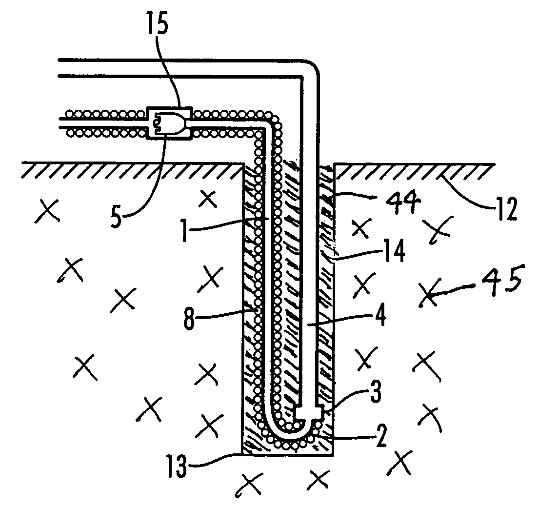
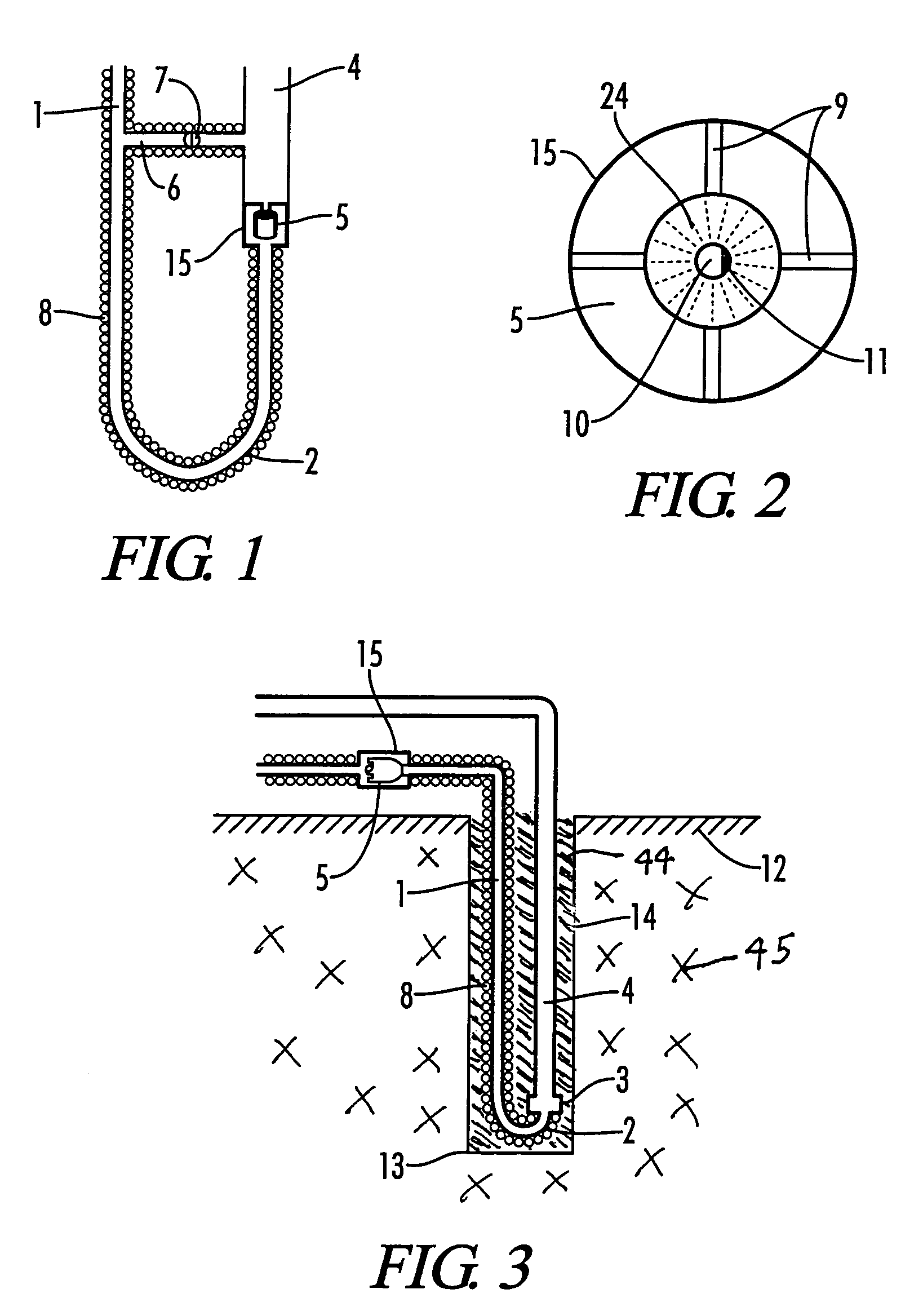
[0067]Referring now to the drawings in detail, where like numerals refer to like parts or elements, there is shown in FIG. 1 a side view of the lower segment of a smaller interior diameter liquid / fluid refrigerant transport line 1, showing a U bend 2 in the liquid line 2 to the point where the casing / housing 15 of a single piston metering device 5 connects the liquid / fluid line 1 with a larger interior diameter vapor / fluid refrigerant transport line 4, for use when a direct expansion heating / cooling system (not shown) is operating in ...


PUM


Abstract

A sub-surface direct expansion geothermal heat exchange unit, which can be placed in sub-surface ground and / or water, consisting of at least one smaller interior diameter refrigerant liquid / fluid transport line with an optional vertically oriented U bend at the bottom, operatively connected to at least one larger interior diameter refrigerant liquid / fluid transport line, with at least one refrigerant flow metering device, designed to the system's compressor's BTU design capacity, which is optionally accessible, installed in the liquid / fluid line at one of an above-surface location and at the sub-surface point near to where the liquid / fluid line connects with the vapor / fluid line, for use when the system is operating in the heating mode, together with a refrigerant flow metering device by-pass means so as to enable additional refrigerant fluid flow at least one of around and past the refrigerant metering device when the system is operating in the cooling mode.

Description

[0001]This application is a continuation-in-part of U.S. patent application Ser. No. 10 / 335,514 filed Dec. 31, 2002, entitled “Sub-Surface And Optionally Accessible Direct Expansion Refrigerant Flow Regulating Device”, which is hereby incorporated by reference in its entirety. All patents, patent applications and publication disclosed or discussed herein are hereby incorporated by reference in their entirety.[0002]A portion of the disclosure of this patent document contains material that is subject to copyright protection. The copyright owner has no objection to the facsimile reproduction by anyone of the patent document or the patent disclosure, as it appears in the Patent and Trademark Office patent file or records, but otherwise reserves all copyright rights whatsoever.BACKGROUND OF THE INVENTION[0003]The present invention relates to an improved sub-surface, or in-ground / in-water, heat exchange means incorporating a sub-surface heating mode refrigerant flow regulating device and ...

Claims


Application Information

Patent Timeline
Patent Type & Authority Patents(United States)
IPC IPC(8): F25D23/12F25B13/00F25B30/06F25B41/04F25B41/06
CPCF24J3/081F25B30/06F25B41/062F25B13/00F25B41/04F25B41/06Y02E10/12F25B2313/002F25B2339/041F25B2400/04F25B2500/11F24T10/10Y02E10/10F25B41/31
Inventor WIGGS, B. RYLAND
Owner EARTH TO AIR SYST
Why Eureka
Try Eureka