Check patentability & draft patents in minutes with Patsnap Eureka AI!

Sheet feeding apparatus and image reading apparatus equipped with the same

a feeding apparatus and image technology, applied in the field of feeding apparatuses, can solve problems such as unusual sounds in the system, sheets to be wrinkled or dirty, and sheets to be creased or stained, and achieve the effect of not lowering the reading performan

Active Publication Date: 2006-07-25
NISCA KK
View PDF4 Cites 43 Cited by
  • Summary
  • Abstract
  • Description
  • Claims
  • Application Information

AI Technical Summary

Benefits of technology

[0011]According to the present invention, in the structure described above, the follower rotating shaft may be supported on a bearing to be movable in a direction toward the drive rotating shaft. The urging means may be formed of an urging spring for urging in a direction with a predetermined angle relative to a direction that the follower rotating shaft moves. Accordingly, the urging spring constituting the urging means presses the follower roller against the drive roller to apply a transport force to the sheets. At the same time, the urging spring deforms the follower rotating shaft, so that the follower roller is inclined in a direction not to cause wrinkle or stain in the sheets.
[0014]According to the present invention, in the structure described above, the transport path sets the sheets according to a center reference in which a center in a direction perpendicular to the transport direction is a reference. The drive and follower rollers positioned at the center are arranged at positions corresponding to the center reference of the sheets. Accordingly, the rollers at the left and right sides apply the transport force to the sheets in an outward direction, thereby preventing wrinkle or noise.
[0015]According to the present invention, in the structure described above, the rollers constituting the drive roller may have an outer diameter larger than those of the rollers constituting the follower roller. Accordingly, when the follower rotating shaft is deformed in a bow shape, the follower roller is deformed along an outer surface of the drive roller, thereby reducing a force 'such as a twisting force applied to the follower roller.
[0017]According to the present invention, a sheet transport apparatus includes a sheet transport path for transporting sheets; a drive roller disposed in the transport path and having a drive rotating shaft connected to drive means; a follower roller contacting the drive roller and having a follower rotating shaft. Each of the drive and follower rollers is formed of three or more rollers spaced in a direction perpendicular to a transport direction. The sheet transport apparatus further includes bearings disposed at left and right sides at an equal distance away from the roller positioned at a center of the follower rotating shaft for supporting both ends of the follower rotating shaft to be movable toward the follower rotating shaft. The sheet transport apparatus further includes urging means for urging the follower rotating shaft in a direction different from a direction that the follower rotating shaft moves. Accordingly, it is possible to deform the follower rotating shaft in a bow shape at the center of the bearings at the left and right sides.
[0019]According to the present invention, a sheet transport apparatus includes a sheet stacker for storing sheets; separating means for separating the sheets stacked on the sheet stacker; a pair of register rollers for temporarily stopping the sheets from the separating means and transporting the sheets further toward a downstream side; and sheet feeding means for feeding the sheets from a pair of the register rollers to a sheet processing platen. The pair of the register rollers is formed of at least two rollers mounted on a drive rotating shaft and a follower rotating shaft. The sheet transport apparatus further includes urging means disposed on the follower rotating shaft for urging the rollers on the follower rotating shaft against the rollers on the drive rotating shaft in the transport direction. Accordingly, the pair of the register rollers can transport the sheets separated at a downstream side of the separating means without causing wrinkle or stain in the sheets.
[0020]According to the present invention, an image reading apparatus includes a transport path for guiding sheets from a sheet stacker to a discharge stacker arranged vertically; a processing platen arranged in the transport path and having photoelectric conversion means for reading images on the sheets; separating means for separating the sheets on the sheet stacker; register means for temporarily stopping the sheets from the separating means and transporting the sheets further toward a downstream side; sheet feeding means for feeding the sheets from the register means to the processing platen; and discharging means for transporting the sheets from the processing platen toward a downstream side. The register means is formed of at least two rollers mounted on each of a drive rotating shaft and a follower rotating shaft. The sheet transport apparatus further includes urging means disposed on the follower rotating shaft for urging the rollers on the follower rotating shaft against the rollers on the drive rotating shaft in the transport direction. Accordingly, it is possible to transport the sheets to the processing platen without lowering reading performance caused by wrinkle or stain.

Problems solved by technology

In the structure having a plurality of rollers to transport the sheets, there are problems of causing the sheets to be wrinkled or dirty.
When the sheets are firmly nipped for transport, it is well known that two (or more) rollers arranged in the sheet width direction may apply unequal pressure to the sheets, thereby causing wrinkle or stain in the sheets or generating unusual sounds in-the system.
Accordingly, it is difficult to form the rollers, and the structure becomes complex.

Method used


Image

  • Sheet feeding apparatus and image reading apparatus equipped with the same
  • Sheet feeding apparatus and image reading apparatus equipped with the same
  • Sheet feeding apparatus and image reading apparatus equipped with the same

Examples


Embodiment Construction

[0032]Hereunder, preferred embodiments of the present invention will be described in detail with reference to the accompanying drawings.

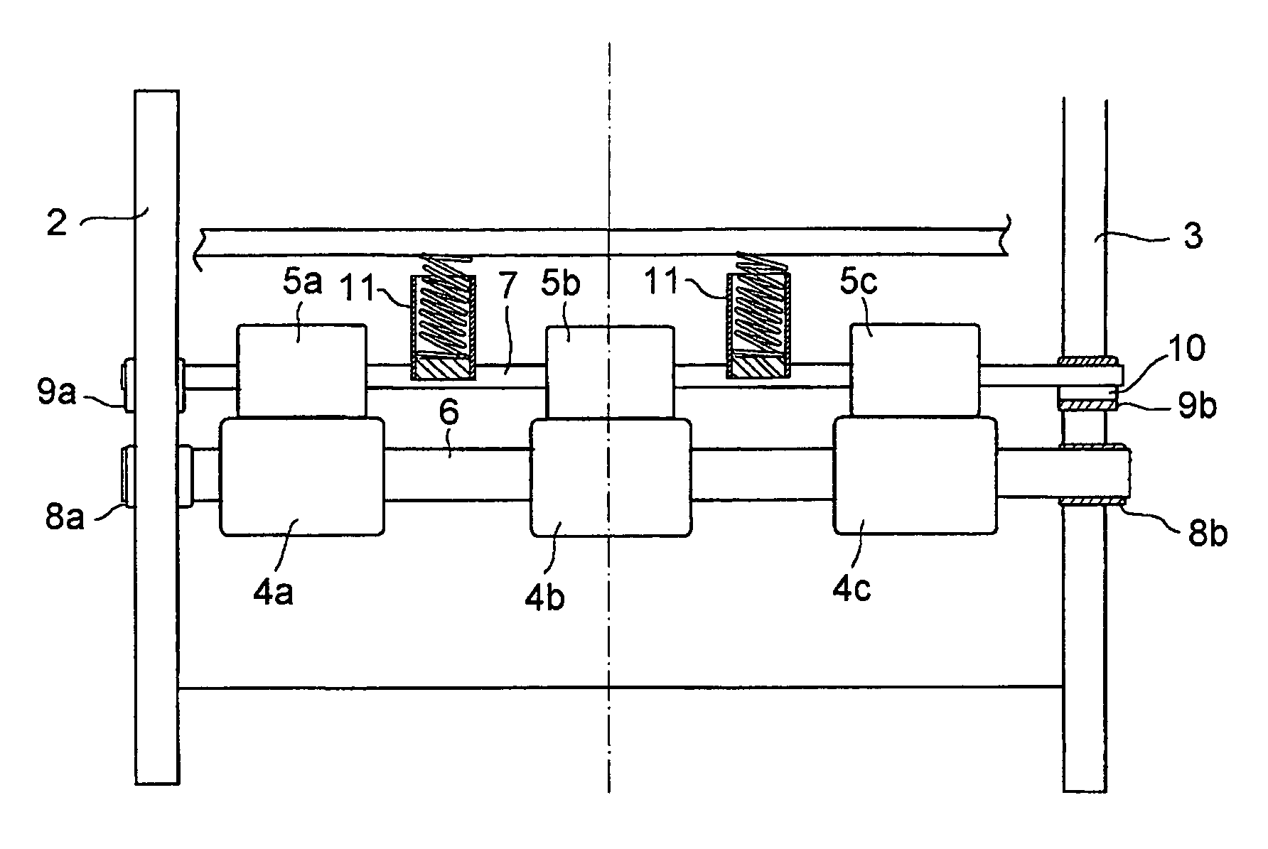
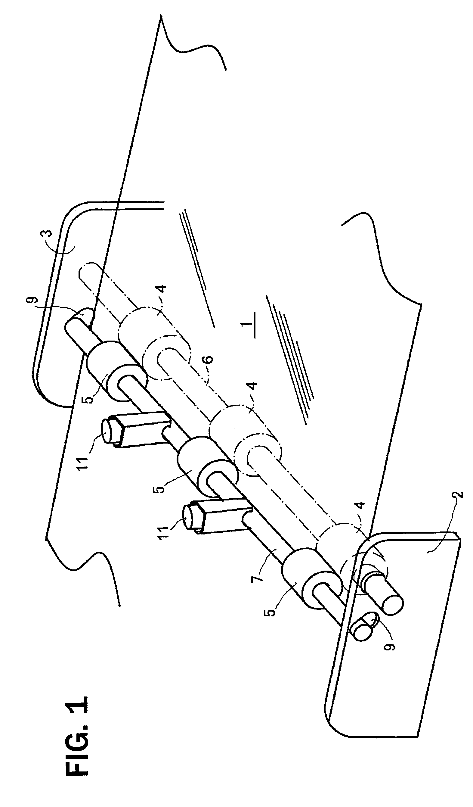
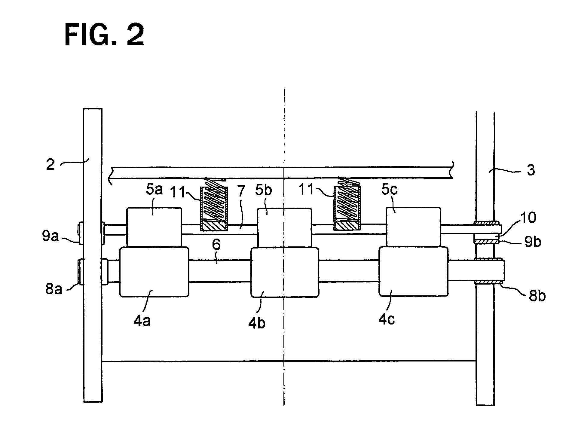
[0033]FIG. 1 and FIG. 2 are views showing a sheet transport apparatus according to an embodiment of the present invention. FIGS. 3(a), 3(b) and 4 show an action of the sheet transport apparatus. In FIG. 1, reference numeral 1 is a guide member constituting sheet transport path, and formed of a pair of plate-shaped members arranged to face each other and form a gap for passing sheets.

[0034]A pair of rollers 4 and 5 is arranged to nip the sheets on the guide member via the guide member 1. One of the rollers is a drive roller 4 and the other is a follower roller 5. The drive rollers 4 are mounted to a drive rotating shaft 6 connected to a drive motor (described later) via a transmission mechanism. The follower rollers 5 are mounted to a follower rotating shaft 7 pressed against the drive rollers 4. The follower rollers 5 are configured to rotate along ...


PUM


Abstract

A sheet transport apparatus includes a transport path for transporting a sheet, and drive and follower roller units disposed in the transport path. The drive roller unit has a drive shaft and at least two drive rollers arranged on the drive shaft in a direction perpendicular to a sheet transport direction. The follower roller unit has a follower shaft and at least two follower rollers contacting the at least two drive rollers. An urging device is attached to the follower shaft for pressing the at least two follower rollers to the at least two drive rollers in a direction with a predetermined angle with respect to the drive shaft.

Description

BACKGROUND OF THE INVENTION AND RELATED ART STATEMENT[0001]The present invention relates to a sheet feeding apparatus for transporting sheets such as a plastic film and, more particularly, relates to a transport roller configuration for transporting sheets in a predetermined direction without damaging the sheets and an image reading apparatus such as a scanner apparatus or copier apparatus equipped with the sheet feeding apparatus.[0002]Generally, a sheet transport apparatus and an image reading apparatuses equipped with a sheet transport apparatus consecutively transport sheets, and include various devices, i.e. a sheet supply unit, sheet processing unit and sheet discharge unit such as a copier, a printing machine or a paper currency handling apparatus, as disclosed, for example, in Japanese Patent Publication (Kokai) No. 08-225221. A variety of methods such as a vacuum transport method, an endless belt method, and a roller method have been used for transporting sheets. As a simpl...

Claims


Application Information

Patent Timeline
Patent Type & Authority Patents(United States)
IPC IPC(8): B65H5/06B65H9/14B65H29/70
CPCB65H5/062B65H2402/54B65H2404/1451B65H2404/1431B65H2404/1341B65H2701/1912
Inventor HAMADA, MASATAKANODA, TETSUYAJINZA, OSAMU
Owner NISCA KK
Features
  • R&D
  • Intellectual Property
  • Life Sciences
  • Materials
  • Tech Scout
  • Unparalleled Data Quality
  • Higher Quality Content
  • 60% Fewer Hallucinations
Learn More