Bend radius friction lock system

a friction lock and bend radius technology, applied in the direction of coupling device connection, coupling/disconnecting parts, electrical apparatus, etc., can solve the problems of extra undesirable downtime, frustration for users, and disconnecting of extension cords from existing electric cords, etc., to achieve the effect of convenient and simple use and inexpensive manufacturing

Active Publication Date: 2006-07-25
PUZIO MICHAEL
View PDF27 Cites 25 Cited by
  • Summary
  • Abstract
  • Description
  • Claims
  • Application Information

AI Technical Summary

Benefits of technology

[0012]A primary objective of the present invention is to provide an improved cord locking device and method of using the device that is easy and simple to use, and inexpensive to manufacture.

Problems solved by technology

A common problem is that when the electric tool or appliance is moved, the extension cord has been known to disconnect from the existing electric cord.
This disconnection can cause extra undesirable downtime and frustration to the user having to stop their work to reconnect the cords to one another.
Additionally, the interconnecting plugs and sockets on the extension cord and / or existing power cord often become damaged since the plug prongs and / or the female sockets can become bent and no longer reliable for future use.
Still furthermore, extension cords are also used for many important applications such as in medical procedures, and such, where untimely disconnections can have disastrous results.
Thus, untimely power cord disconnections can be both inconvenient and even dangerous.
However, there are problems with tying knots in electrical cords.
Further, it can be difficult and time consuming to both tie and to untie, the cords from one another, as well as the knots create an unsightly appearance.
Still furthermore, small and / or tight knots can cause the plugs to break off from the wire.
However, each of these devices requires the user pass the cord down and up and / or up and down along a single column of side extending slots.
However, this device can also easily fail since the C-shaped ends have thin tip portions that can easily break off over time from enough pulling tension resulting in the cords separating from one another.
Also, the cords are tied together in a straight line by a device having openings to the same side, which is also not desirable for similar reasons to the other straight line attachments devices previously described.
However, these devices require bending and / or snapping various components such as prongs about the cords that can become broken and / or worn overtime thus causing the devices to not being reusable.
Also, these devices still require the user have both cords arranged in a single straight line, that similar to the above devices can become disconnected when being pulled apart and / or if the cord diameter is much smaller than the prong holder diameter being used.
Additionally, these fixed size devices do not work on all sizes of cords since cords and / or the plugs can come in a variety of sizes.
Thus, some cords and / or plugs may be too large or too small to be supported by these devices.
However these devices require additional assembly by having to combine plural components together which adds extra manufacturing costs and expense to the consumer.
Additionally, having plural components raises the possibility that these devices cannot work when any of the components such as the rotating clip in Mendez or the clamping body in Stekelenburg becomes separated and / or lost and / or broken over time.
Also, the shapes of these devices are not suitable to be placed and / or moved smoothly around corners and / or steps.
However, this device can easily fail when one of the hook members and / or eyelets breaks off which can occur when enough pulling tension occurs to the cords.
Additionally, this device takes up additional space by requiring the interconnected plug and socket to be located to the side of the device.
Also, the shape of this device is not suitable to be placed and / or moved smoothly around corners and / or steps.
None of these patents overcomes all the problems with the prior art described above.

Method used


Image

  • Bend radius friction lock system
  • Bend radius friction lock system
  • Bend radius friction lock system

Examples


Embodiment Construction

[0050]Before explaining the disclosed embodiments of the present invention in detail it is to be understood that the invention is not limited in its applications to the details of the particular arrangements shown since the invention is capable of other embodiments. Also, the terminology used herein is for the purpose of description and not of limitation.

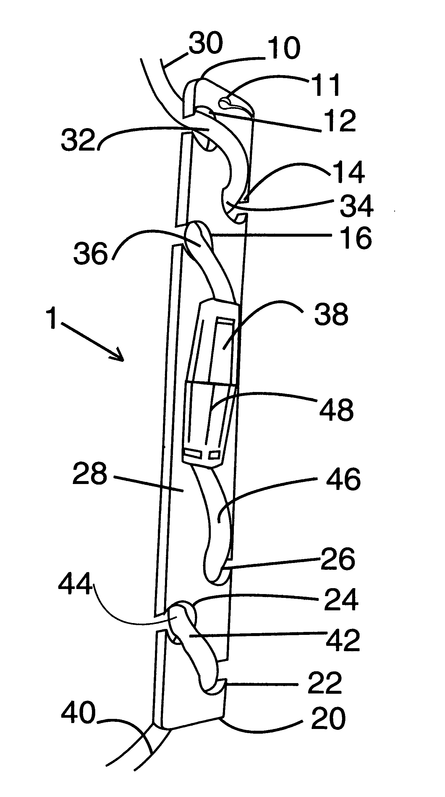
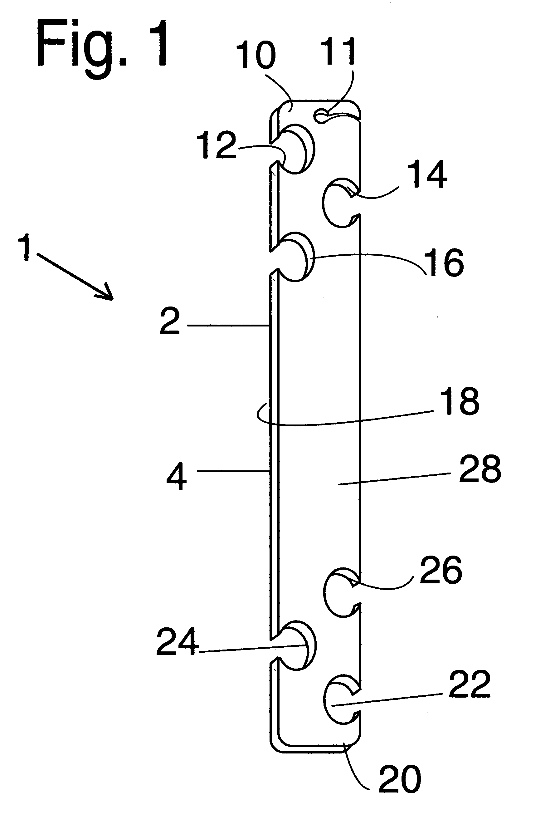
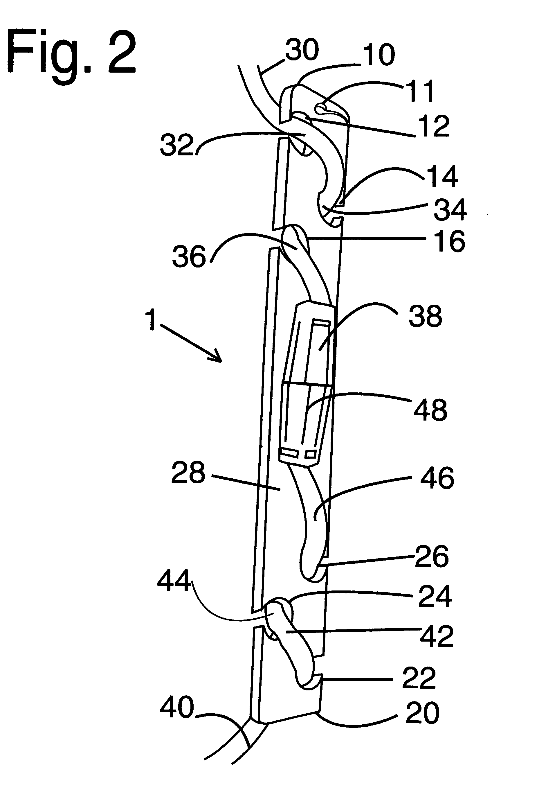
[0051]FIG. 1 is a perspective view of a first preferred embodiment of an elongated planar locking device 1 with alternating side edge facing curved slots 12, 14, 16 on one end 10, and alternating side edge facing curved slots 22, 24, 26 on an opposite end 20. The device 1 can have similar dimensions to a small ruler being approximately 8 to approximately 16 inches in length and approximately 1 / 10 to approximately ½ inch in thickness. Device 1 can include a small hanging slot portion 11 at one end when the device is hung from a hook in a retail store, and / or for allowing the user to hang the device from a fastener such as a nail, a h...


PUM


Abstract

Locking devices and methods of using the devices for interlocking two, three, four or more electrical type extension cords together with each other and/or with electrical cords on appliances and tools, to one another. Versions of the devices can include side facing slots having various configurations that allow portions of the electrical cords to be wrapped around and snappably held within. Pulling the cords apart can tighten the cords into the slots. The devices can have various configurations such as being ruler shaped, fan shaped ends, fork shaped ends, and the like. Coils and springs can be located on the ends of the devices in place of the slots to also allow for the cords to be locked. Indicia ruler markings can be provided on the device so that it can be used as a measuring tool.

Description

[0001]This invention relates to electric cords, in particular to devices and methods of interlocking separate electric power cords together so that the cords do not detach from one another.BACKGROUND AND PRIOR ART[0002]Extension cords have become very popular over the years for connecting to existing electric cords on various power equipment such as but not limited to power tools and / or appliances to remotely located electrical outlets. A common problem is that when the electric tool or appliance is moved, the extension cord has been known to disconnect from the existing electric cord. This disconnection can cause extra undesirable downtime and frustration to the user having to stop their work to reconnect the cords to one another. Additionally, the interconnecting plugs and sockets on the extension cord and / or existing power cord often become damaged since the plug prongs and / or the female sockets can become bent and no longer reliable for future use. Still furthermore, extension c...

Claims


Application Information

Patent Timeline
Patent Type & Authority Patents(United States)
IPC IPC(8): H01R13/62
CPCH01R13/6392H01R13/5833
Inventor PUZIO, MICHAEL
Owner PUZIO MICHAEL
Why Eureka
Try Eureka