Differential apparatus

a technology of differential gearings and gearings, which is applied in the direction of differential gearings, transmission elements, belts/chains/gearings, etc., can solve the problems of high cost and complexity of heat treatment of whole teeth, or the selection of materials with high strength is required for coping with uneven high load, so as to improve the durability of clutch teeth, reduce the number of parts, and high installation accuracy

Active Publication Date: 2006-07-25
TOCHIGI FUJI IND CO LTD
View PDF19 Cites 25 Cited by
  • Summary
  • Abstract
  • Description
  • Claims
  • Application Information

AI Technical Summary

Benefits of technology

[0009]It is, therefore, an object of this invention to solve the problems of the related differential apparatus as stated above. Further, the object is also to provide a differential apparatus which make it possible to obtain a high accuracy of installation while reducing the number of parts, and further to improve durability of the clutch teeth while uniformly transmit the power.
[0012]Further, according to this invention, the junction includes a second connecting wall that is formed between the adjacent pinion shafts, and the second connecting wall restricts an rotational movements of the pinion shafts relative to the other of the pinion shaft.

Problems solved by technology

Therefore, while a high working accuracy of the pinion shaft holes is required to avoid any uneven transmission of a load to the teeth on the dog clutch 31, the expensive and complicated heat treatment of the whole teeth or the selection of a material with high strength is required for coping with an uneven high load.

Method used


Image

  • Differential apparatus
  • Differential apparatus
  • Differential apparatus

Examples


first embodiment

(First Embodiment)

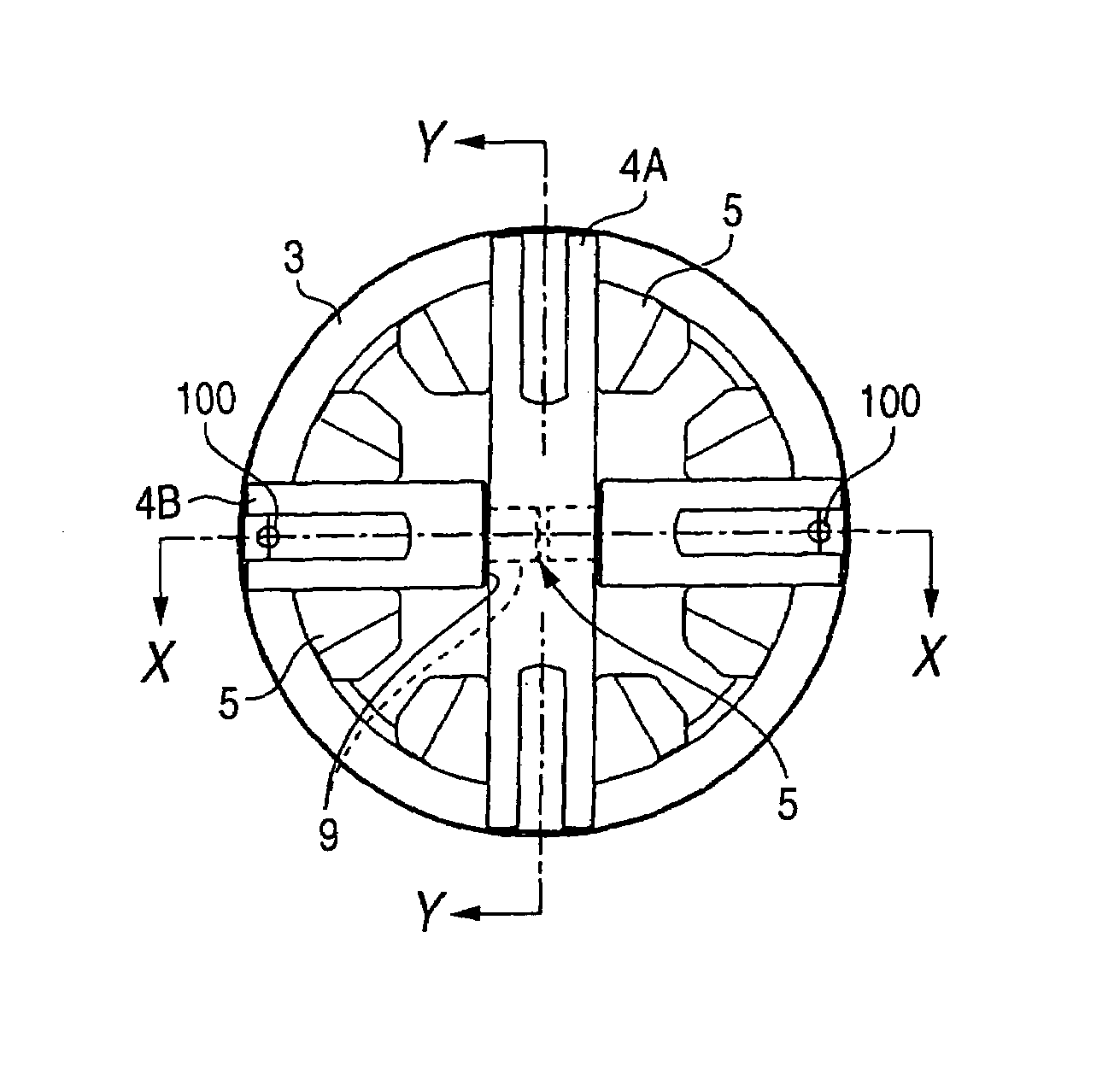
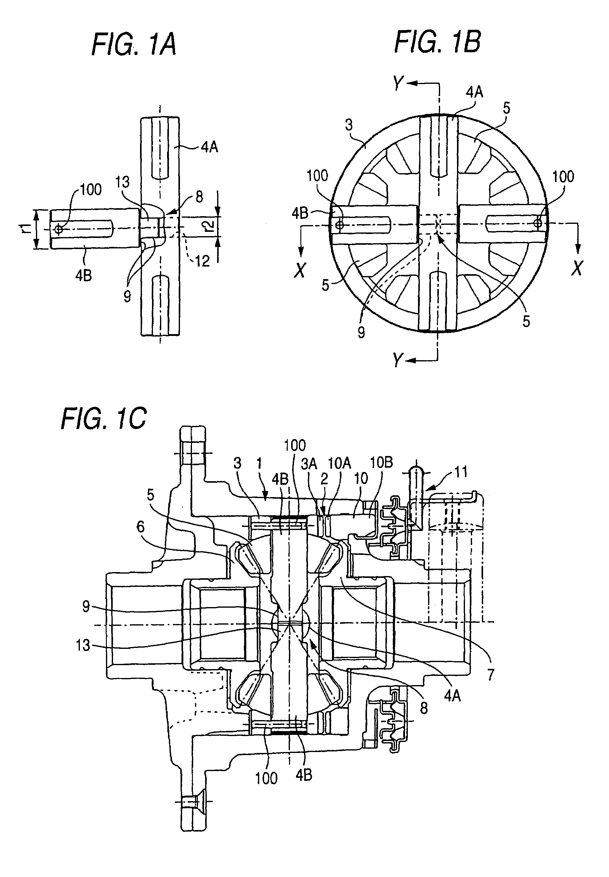
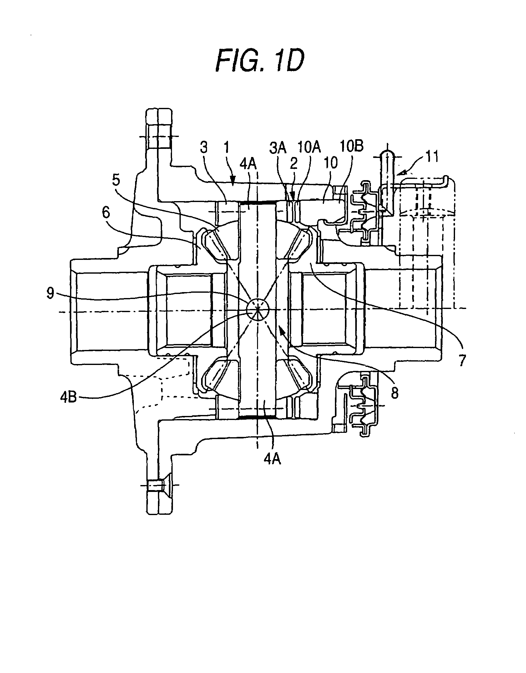
[0022]FIG. 1A, FIG. 1B, FIG. 1C and FIG. 1D show the differential apparatus according to a first embodiment of this invention, and FIG. 1A shows a junction of pinion shafts, FIG. 1B is a cross sectional view showing the pinion shafts and pinions as attached to an inner differential as an inner rotary member, FIG. 1C is an overall sectional view of the differential apparatus that is taken along a line X—X of FIG. 1B, and FIG. 1D is an overall sectional view of the differential apparatus that is taken along Y—Y of FIG. 1B. This embodiment is one example wherein this invention is applied to a free running differential. In the free running differential it is possible, by the engagement or disengagement of a clutch tooth, to achieve a two-wheel drive mode without transmitting a rotary driving force from a differential case to a differential mechanism comprising a differential gear, or a four-wheel drive mode by transmitting it.

[0023]More specifically, as shown in FIG. 1...

second embodiment

(Second Embodiment)

[0033]FIG. 2A; FIG. 2B, FIG. 2C and FIG. 2D show a differential apparatus according to a second embodiment of this invention. According to this embodiment, a junction 8 in the center of rotation between a long pinion shaft 4A and short pinion shafts 4B comprises, a small diameter portion 14 and an arcuate groove 16, as shown in FIG. 2A. The small diameter portion 14 is formed in the mid-portion of the long pinion shaft 4A. The arcuate groove 16 is formed in the axial end of the short pinion shaft 4B. The arcuate groove 16 contacts the peripheral surface of the small diameter portion 14 in a complementary fashion. The long pinion shaft 4A is fitted in the inner differential 3, and the short pinion shafts 4B are fitted in the inner differential 3 at right angles to the long pinion shaft 4A. And, the short pinion shafts 4B and the inner differential 3 are fixed by pins 100. Accordingly, a uniform power transmitting portion 9 for ensuring and maintaining the perpendic...

third embodiment

(Third Embodiment)

[0039]FIG. 3A, FIG. 3B, FIG. 3C and FIG. 3D show a differential apparatus according to a third embodiment of this invention. According to this embodiment, a junction 8 in the center of rotation between a long pinion shaft 4A and short pinion shafts 4B comprises a pair of grooves 17 formed back to back in the mid-portion of the long pinion shaft 4A for receiving the outside diameter of the short pinion shaft 4B therein in a complementary way. The grooves 17 include bottom surfaces, respectively. Axial end surfaces of the short pinion shafts 4B contact with the bottom surfaces of the grooves 17 of the long pinion shaft 4A. The long pinion shaft 4A is fitted in the inner differential 3, and the short pinion shafts 4B are fitted in the inner differential 3 at right angles to the long pinion shaft 4A. And, the short pinion shafts 4B and the inner differential 3 are fixed by pins 100. Accordingly, a uniform power transmitting portion 9 for ensuring and maintaining the pe...


PUM


Abstract

A junction at which the pinion shafts are connected to each other by themselves is formed in a portion of the rotational axis of an outer rotary member where the pinion shafts meet each other. Therefore, the positional relation of the pinion shafts without any substantial error is reliably secured and maintained, and the uniform transmission of power to the pinion shafts becomes possible. Accordingly, the number of parts is reduced, and it is not necessary to give any heat treatment to the clutch tooth or select any material of high strength therefor.

Description

BACKGROUND OF THE INVENTION[0001]This invention relates to a differential apparatus having radially arranged pinion shafts rotatably supporting pinions disposed between and meshing with a pair of side gears.[0002]This kind of differential apparatus, having radially arranged pinion shafts rotatably supporting pinions disposed between and meshing with a pair of side gears, is often used as a differential apparatus for a vehicle, since it is simple in construction and inexpensive. This kind of differential apparatus performs differential actions by bevel tooth engagement between a pair of side gears and pinions. Further, this kind of differential apparatus may perform the function of stopping those differential actions (differential lock: dif. lock) (see, for example, JP-A-10-096461), or stopping the transmission of power (cutting off power in a free running differential).[0003]An example of a differential lock mechanism as disclosed in JP-A-10-096461 is described briefly with referenc...

Claims


Application Information

Patent Timeline
Patent Type & Authority Patents(United States)
IPC IPC(8): F16H48/08F16H48/24F16H48/30
CPCF16H48/08F16H48/24F16H48/30F16H48/34F16H48/32F16H2200/2071F16H2048/082F16H2048/085F16H2048/204F16H2048/382F16H48/40
Inventor SUDOU, NORIYUKI
Owner TOCHIGI FUJI IND CO LTD
Why Eureka
Try Eureka