Method and apparatus for lighting a discharge lamp

Inactive Publication Date: 2006-07-25
AMPR
View PDF39 Cites 32 Cited by
  • Summary
  • Abstract
  • Description
  • Claims
  • Application Information

AI Technical Summary

Benefits of technology

[0008]The present invention solves these and other problems by providing a compact, cost-effective, efficient, and reliable circuit which is compatible with existing lighting systems for discharge lamps. In one embodiment, an energy efficient ballast (or an electronic ballast) drives a discharge lamp, such as, for example, a T-8 or T-12 fluorescent lamp. The energy efficient ballast includes an inverter (or an oscillator or a co

Problems solved by technology

The ballast circuit for low frequency operation is generally bulky and operates the discharge lamps inefficiently.
The higher frequency AC signal requires less current to flow through the discharge lamps to achieve the same light output, and lower current flows can lengthen the life of the discharge lamps.
Generally, electronic ballast circuits are much more expensive than magnetic ballast

Method used


Image

  • Method and apparatus for lighting a discharge lamp
  • Method and apparatus for lighting a discharge lamp
  • Method and apparatus for lighting a discharge lamp

Examples


Embodiment Construction

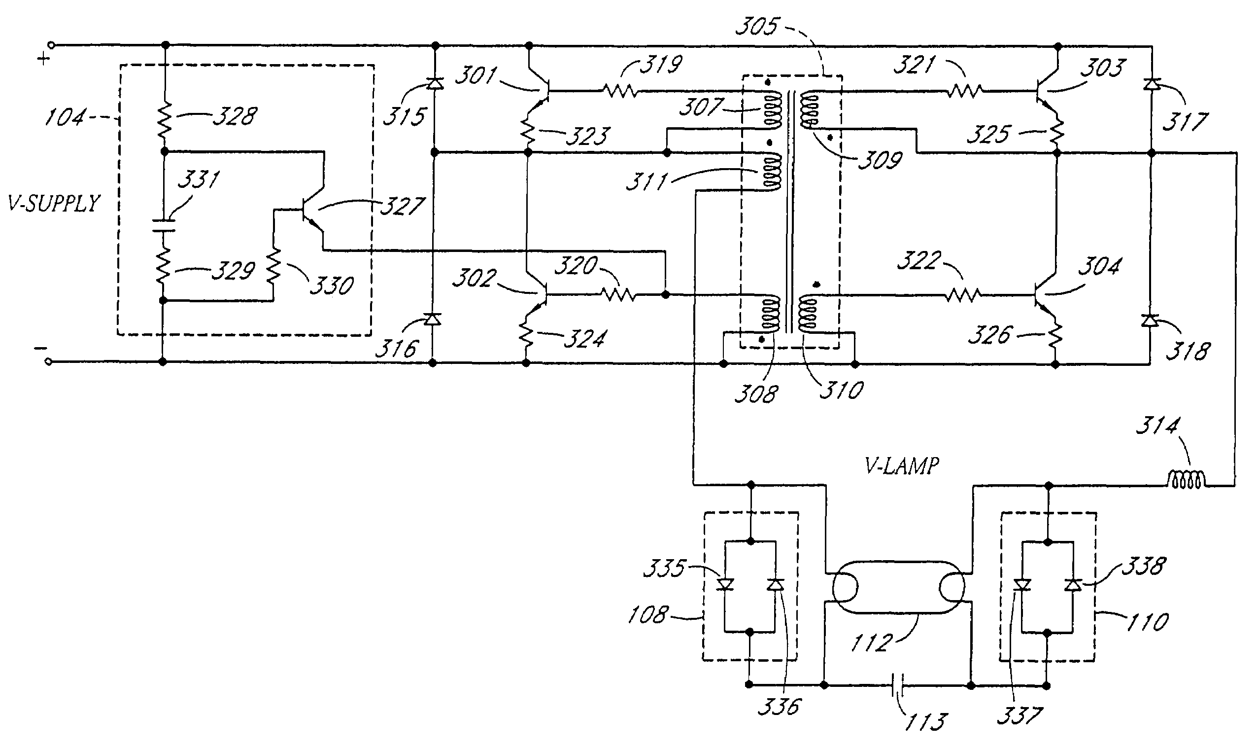
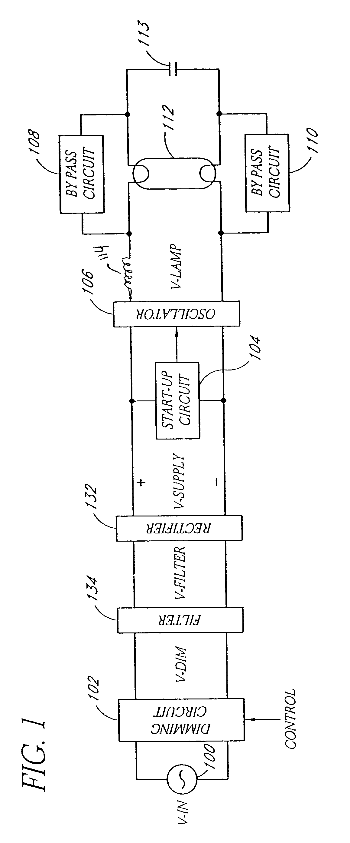
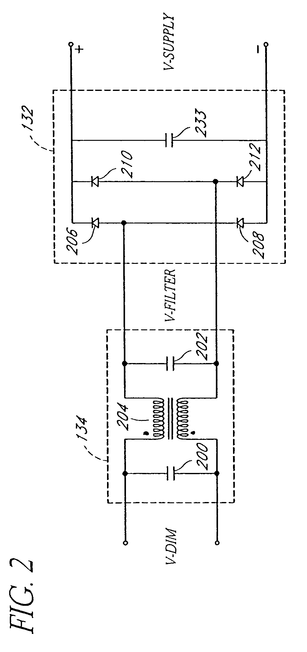
[0027]Embodiments of the present invention will be described hereinafter with reference to the drawings. FIG. 1 is a block diagram of one embodiment of a lighting system for driving a wide range of discharge lamps 112, such as, for example, fluorescent lamps. The lighting system advantageously accepts a wide range of input voltages (including for example, AC input signals from a power line) and produces an AC output signal with a frequency and / or voltage that can be different from the AC input signal provided by the power line. The lighting system can include an optional dimming circuit 102, a filter circuit 134, a rectifier circuit 132, a start-up circuit 104, an oscillator circuit 106, and bypass circuits 108, 110. In one embodiment, the bypass circuits 108, 110 comprise back-to-back diodes. In one embodiment, the bypass circuits 108, 110 comprise capacitors.

[0028]In one embodiment, the dimming circuit 102 is coupled to an AC input voltage (V-IN) 100 of relatively low frequency (f...


PUM


Abstract

A reliable and efficient circuit for lighting a discharge lamp is described. An inverter accepts a direct current supply voltage and outputs an alternating current lamp voltage to drive the discharge lamp at a relatively high frequency. In one embodiment, the inverter includes semiconductor switches in a full-bridge configuration, a transformer feedback circuit to control the semiconductor switches, and a series L-C resonant circuit. In one embodiment, the inverter includes semiconductor switches in a half-bridge configuration, a transformer feedback circuit to control the semiconductor switches, and a series L-C resonant circuit. The inverter can drive multiple discharge lamps in a parallel configuration. A bypass circuit can also be coupled across a cathode of the discharge lamp to extend the life of the discharge lamp. The bypass circuit activates when a lamp cathode wears out.

Description

RELATED APPLICATION[0001]The present application is a divisional of U.S. application Ser. No. 10 / 205,290, filed Jul. 23, 2002 now U.S. Pat. No. 6,371,075, which claims priority benefit under 35 U.S.C. § 119(e) of Provisional Application No. 60 / 339,717, filed Nov. 2, 2001.BACKGROUND OF THE INVENTION[0002]1. Field of the Invention[0003]The present invention relates to a circuit for lighting a discharge lamp and, in particular, refers to an electronic ballast circuit for fluorescent lamps.[0004]2. Description of the Related Art[0005]Discharge lamps (for example, fluorescent lamps) provide light in numerous commercial, industrial, and consumer applications. The discharge lamps are illuminated when driven by an alternating current (AC) signal, such as signals from a power line which oscillate at a relatively low frequency (for example, 60 Hertz). The discharge lamps typically need a ballast circuit (for example, a magnetic ballast circuit) to interface with the power line. The ballast ci...

Claims


Application Information

Patent Timeline
IPC IPC(8): H05B39/00H05B41/282H05B41/298H05B41/36
CPCH05B41/245H05B41/2827H05B41/36H05B41/2988Y10S315/04
Inventor PAK, VENIAMIN A
Owner AMPR
Why Eureka
Try Eureka