
Microarray detector and synthesizer

a microarray and detector technology, applied in the direction of radiation measurement, optical radiation measurement, spectral modifiers, etc., can solve the problems of large data processing overhead, large image data manipulation overhead, and further complicated methods, so as to enhance the signal to noise ratio, and minimize the amount of informative data

Inactive Publication Date: 2006-07-25
GENE READER LLC
View PDF32 Cites 140 Cited by
  • Summary
  • Abstract
  • Description
  • Claims
  • Application Information

AI Technical Summary

Benefits of technology

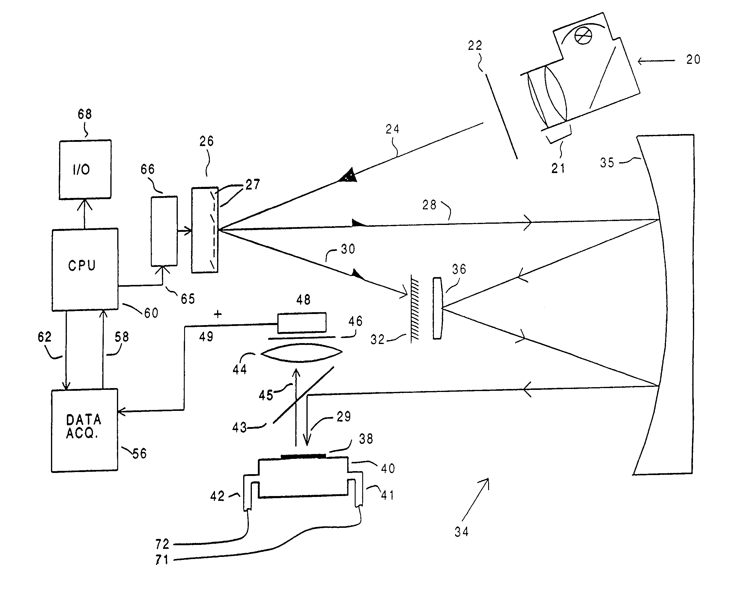
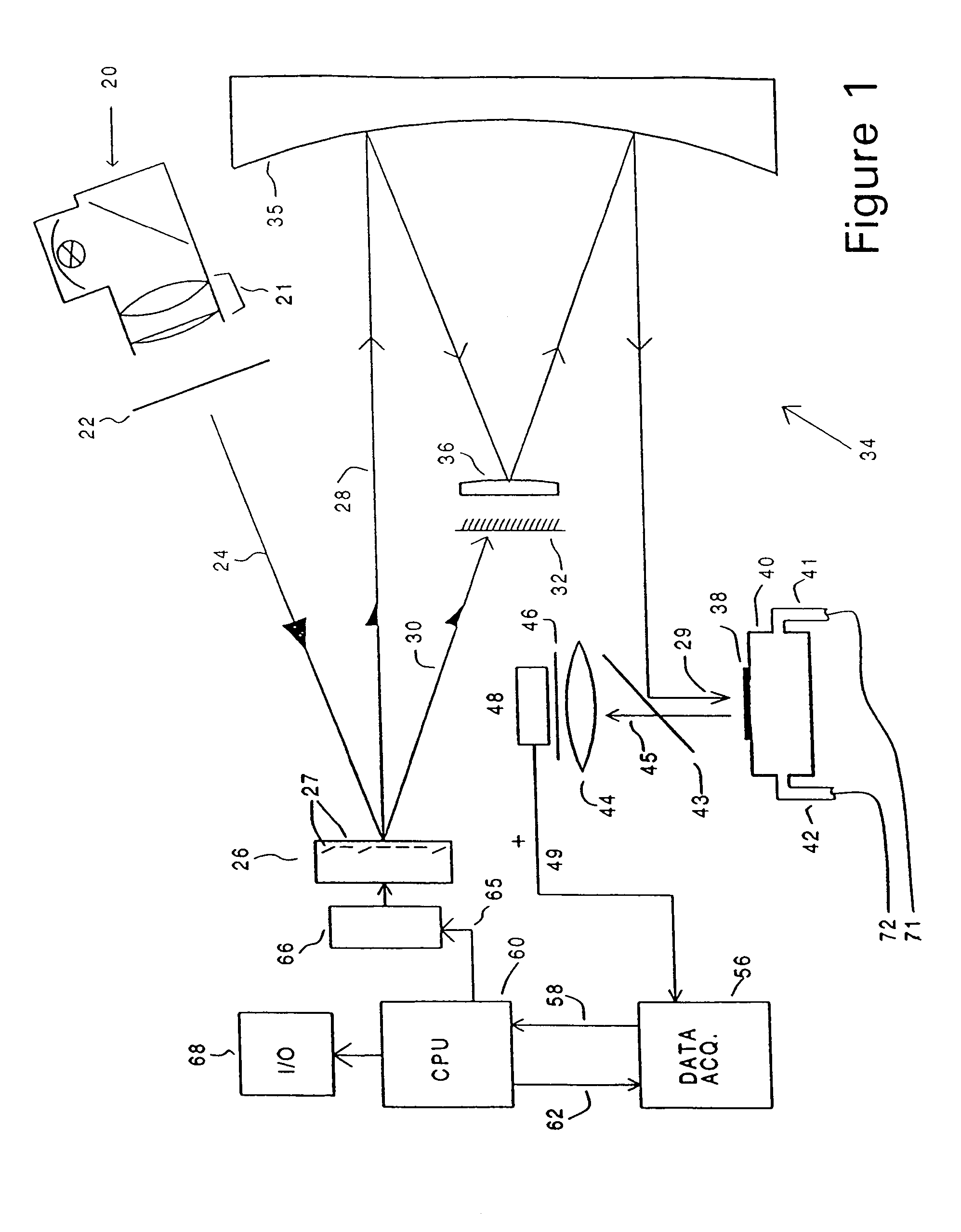
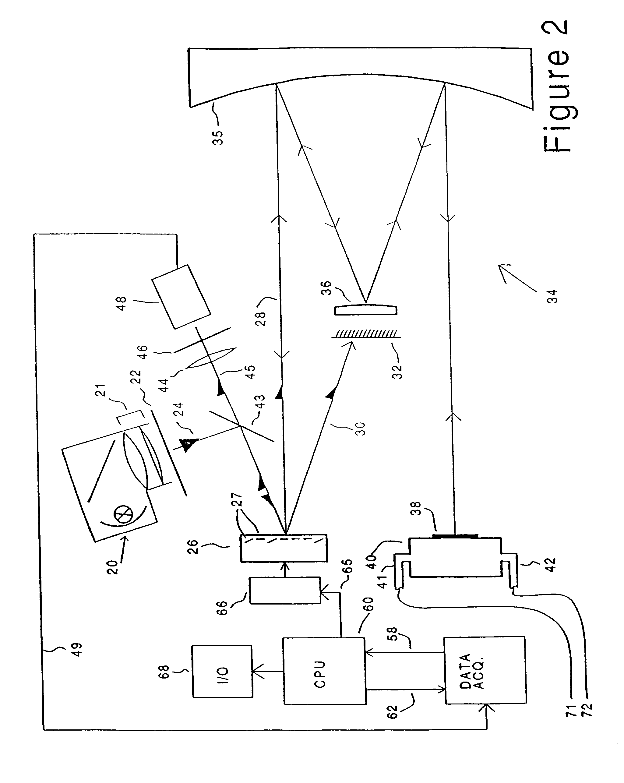
[0022]As described above, the present invention provides systems for comparing data from two or more locations on a microarray such that the information can be efficiently processed, stored, and / or interpreted. With respect to such embodiments, the present invention provides a system of comparing optical signals from two or more locations on a patterned microarray comprising: a spatial light modulator capable of receiving light from a light source and capable of directing at least a portion of said light to one or more locations on a patterned microarray and a detector capable of detecting an optical signal obtained from a patterned microarray. The system may further comprise any of the additional components described herein. In preferred embodiments, the detector is capable of receiving optical signals obtained from one or more locations on the patterned microarray. The present invention is not limited in the manner by which the optical signal is received. For example, in some embodiments, there is sequential receipt of optical signal from each of the two or more locations (e.g., wherein the system further comprises a processor capable of generating processed data, where the processed data comprises data obtained from a first location of said microarray mathematically transformed with data obtained from a second location of said microarray). In other embodiments, there is simultaneous receipt of optical signal from each of the two or more locations (e.g., optical signal from two or more sites is detected together—i.e., additively).

Problems solved by technology

Obviously, the analysis of such microarrays with current scanning devices generates large volumes of data.
Manipulation of image data of this size represents a significant data processing overhead.
Such methods are further complicated when a high-density microarray must be scanned piecemeal, with individual portions of the image subsequently fitted together.
For large-scale analysis, such methods require substantial computer memory storage.
Furthermore, current microarray scanners are large, cumbersome, and expensive, making large-scale analysis time consuming, complex, and inefficient.

Method used


Image

  • Microarray detector and synthesizer
  • Microarray detector and synthesizer
  • Microarray detector and synthesizer

Examples


Embodiment Construction

[0110]The present invention utilizes a light source, spatial light modulator, microarray, and a detector in the reading and synthesis of microarrays. For example, the present invention provides micromirror systems for synthesizing and detecting nucleic acid microarrays and systems for collecting, processing, and analyzing data obtained from a microarray. Certain preferred embodiments of the systems, devices, and methods of the present invention are described in more detail below in the following sections: I) Synthesis; II) Hybridization; III) Detection; and IV) Exemplary System Configurations. The following examples are provided in order to demonstrate and further illustrate certain preferred embodiments and aspects of the present invention and are not to be construed as limiting the scope thereof.

[0111]I. Synthesis

[0112]Microarrays provide a powerful tool for the analysis of numerous types of biomolecules, as well as other organic and inorganic samples. Analysis of nucleic acids is...


PUM

PropertyMeasurementUnit
sizeaaaaaaaaaa
pixel sizeaaaaaaaaaa
surface areaaaaaaaaaaa

Abstract

The present invention relates to novel systems, devices, and methods comprising spatial light modulators for use in the reading and synthesis of microarrays. For example, the present invention provides micromirror systems for synthesizing and acquiring data from nucleic acid microarrays and systems for collecting, processing, and analyzing data obtained from a microarray.

Description

[0001]The present application is a continuation of U.S. application Ser. No. 10 / 408,870 filed Apr. 8, 2003, now U.S. Pat. No. 6,806,954, which is a continuation of U.S. application Ser. No. 09 / 679,858 filed Oct. 5, 2000, now U.S. Pat. No. 6,545,758, which is a continuation-in-part of application Ser. No. 09 / 640,617 filed Aug. 17, 2000 now U.S. Pat. No. 6,567,163, the specifications of which are herein incorporated by reference in their entireties.FIELD OF THE INVENTION[0002]The present invention relates to novel systems, devices, and methods comprising spatial light modulators for use in the reading and synthesis of microarrays. For example, the present invention provides micromirror systems for synthesizing and acquiring data from nucleic acid microarrays and systems for collecting, processing, and analyzing data obtained from a microarray.BACKGROUND OF THE INVENTION[0003]Biology and medicine have entered the age of the genomics. The completion, and imminent completion, of genomes ...

Claims


Application Information

Patent Timeline
Patent Type & Authority Patents(United States)
IPC IPC(8): G01N21/64
CPCG01N21/6456B82Y30/00C40B60/08G01J3/02G01J3/021G01J3/0229G01N21/6428G01N21/645G01N21/6452B01J2219/00378B01J2219/00439B01J2219/00527B01J2219/00576B01J2219/00605B01J2219/00608B01J2219/0061B01J2219/00612B01J2219/00619B01J2219/00626B01J2219/00639B01J2219/00659B01J2219/00675B01J2219/00693B01J2219/00704B01J2219/00711B01J2219/00722B01J2219/00725B01J2219/00387
Inventor SANDSTROM, PERRY
Owner GENE READER LLC
Learn More