Method of detecting, and a receiver for, a spread spectrum signal

a spread spectrum and receiver technology, applied in the direction of synchronisation arrangement, instruments, measurement devices, etc., can solve the problems of increasing power consumption and complexity, increasing power consumption, increasing time delay, etc., and achieve the effect of avoiding the higher power consumption and circuit complexity

Active Publication Date: 2006-07-25
ATREUS LABS LLC
View PDF5 Cites 0 Cited by
  • Summary
  • Abstract
  • Description
  • Claims
  • Application Information

AI Technical Summary

Benefits of technology

[0013]The interpolation and matching need not be performed over the duration of a complete chip sequence, but may be performed over a shorter duration in the region of a peak in the weighted average values of the absolute values of the filtered samples, thereby avoiding the higher power consumption and circuit complexity of interpolating and matching over the duration of a complete chip sequence.

Problems solved by technology

A higher resolution can be achieved by increasing the sampling rate, but at the expense of increased power consumption and complexity A higher resolution can also be obtained by averaging over measurements made on several occurrences of the chip sequence in the received signal, but at the expense of increased power consumption and increased time delay.

Method used


Image

  • Method of detecting, and a receiver for, a spread spectrum signal
  • Method of detecting, and a receiver for, a spread spectrum signal
  • Method of detecting, and a receiver for, a spread spectrum signal

Examples


Embodiment Construction

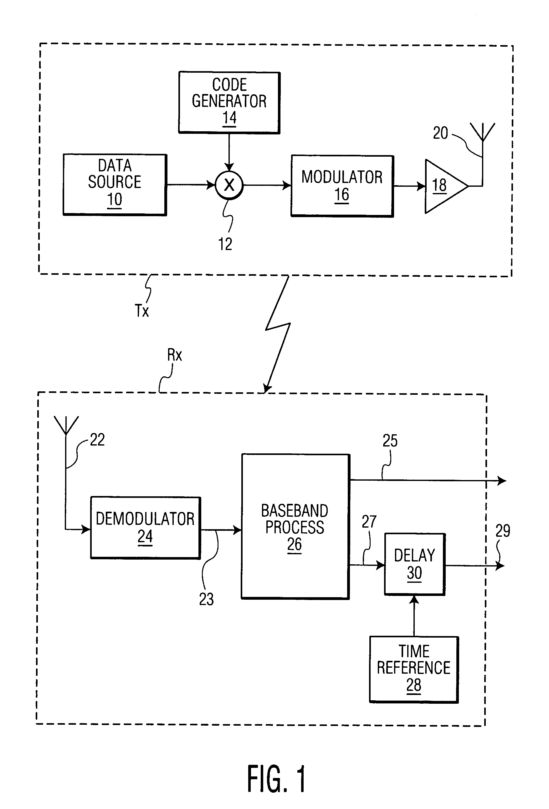
[0025]Referring to FIG. 1, the spread spectrum system comprises a transmitter Tx and a receiver Rx. The system uses a C chip P-N (psuedo-noise) sequence for spreading. For convenience of description it will be assumed that the system operates in the 2.4 GHz ISM band with a bit rate of 200 kbit.s−1, with the signal spread to 2.2 MHz using a sequence of 11 chips (C=11) at a chip rate of 2.2 Mchip.s−1. The transmitter Tx comprises a data source 10 which produces symbols in the form of bits at 200 kbit.s−1. The symbols are supplied to a mixer 12 to which is connected a code generator 14 which supplies an 11 chip P-N sequence. The 2.2 MHz spread signal is supplied by the mixer 12 to a GFSK modulator 16, the output of which is a modulated radio signal which is amplified in a power amplifier 18 and propagated by an antenna 20. In the course of being propagated the radio signal will be subject to noise and distortion.

[0026]At the receiver Rx, the propagated radio signal is received by an an...


PUM


Abstract

A method of detecting, and a receiver for, a spread spectrum signal, in which a chip sequence is sampled (110) and filtered in a matched filter (120), the output of the filter is averaged (130) over respective samples of successive chip sequences, sub-samples are determined (180) by interpolating between the averaged samples, and the position of the chip sequence in the spread spectrum signal is determined (170) by determining the position of closest match between the sub-samples and samples taken at the same interval from a reference correlation function (160) of the chip sequence. The time of arrival of the spread spectrum signal may be determined by comparison of the position of the chip sequence, or an average of more than one such position, with a time reference. The position of closest match may be determined by correlation.

Description

FIELD OF THE INVENTION[0001]The present invention relates to a method of detecting a spread spectrum signal and to a receiver for a spread spectrum signal, and has application in, for example, apparatus for estimating the time of arrival of a signal, apparatus for estimating the distance travelled by signal from a transmitter to a receiver, and in location determining apparatus.BACKGROUND AND SUMMARY OF THE INVENTION[0002]It is known to detect a spread spectrum chip sequence by correlating a received signal with a reference signal, the peak of the correlation function indicating detection of the sequence. Typically, the detection is performed using samples of the received signal and of the reference signal. Due to sampling, the maximum resolution for determining the position of the sequence in the received signal is ±0.5 sample interval. For example, a sequence transmitted at a chip rate of 2.2 Mchip.s1 and sampled in the receiver at 22 Msample.s−1 would give a detection resolution ...

Claims


Application Information

Patent Timeline
Patent Type & Authority Patents(United States)
IPC IPC(8): H04B1/69G01S11/08H04B1/707H04W36/00H04W56/00
CPCH04B1/7093G01S11/08H04B1/70757H04B1/7077
Inventor WHIGHT, KENNETH R.
Owner ATREUS LABS LLC
Why Eureka
Try Eureka