Real time total asset visibility system

a total asset and asset technology, applied in the field of real-time total asset visibility system, can solve the problems of limiting the information which can reasonably be displayed, partially defeating the goal of efficient inventory, and commonly recognized as being inefficient and cumbersome, and achieve the effect of quick and effective establishmen

Inactive Publication Date: 2006-07-25
GHAFFARI TOURAJ
View PDF28 Cites 56 Cited by
  • Summary
  • Abstract
  • Description
  • Claims
  • Application Information

AI Technical Summary

Benefits of technology

[0021]Further, both the passive and active tags may have common operative features such as multi-frequency capabilities wherein the activation or power-up field or signal is generated at the aforementioned first frequency and communication between the tag and the reader, either in a uni-directional or bi-directional mode, occurs at a second, differing frequency. The existence of the multi-frequency capabilities of the various tags enhances the range or proximity in which communication, activation, power-up, etc, may occur.
[0022]More specifically, FCC regulations prohibit the generation or transmission of pulsed signals, for example between a reader and a tag, except when licensing requirements are met. However FCC regulations do allow for the generation of fields / signals of certain frequencies, having pre-established band parameters, to be transmitted or generated at increased field strengths. Therefore, establishing a field strength of “unlimited radiated energy” within the frequency parameters specified is permitted. In other words, increased power can be utilized within certain specified frequency ranges, including 13.56 MHz. to increase the range in which the tags of a monitoring system can be detected, activated, powered-up, etc. without violating FCC regulations. Accordingly, activation signals or the establishment of electric fields for the activation or “wake-up” and / or “power-up” of one or a plurality of RF responsive tags can be accomplished using increased field strengths as long as there is no human exposure hazards involved. Therefore, utilizing the aforementioned first frequency in the frequency range of 13.56 MHz. allows for the activation and / or powering (such as in passive tags) at a much higher energy level so as to increase the read distance and / or proximity range to at least approximately 12 to 15 feet without violating any regulatory codes. It is emphasized that while the aforementioned first frequency, in the frequency range of 13.56 MHz may be preferred due to the ability to use the higher energy level and thereby increase the read distance, other frequencies can be utilized to activate or power the tags, wherein such frequency may be in the range of 433 Mhz.
[0024]As set forth above, the various embodiments of the present invention may further comprise a tracking system demonstrating certain control and tracking abilities. More specifically, the reader assembly may include at least one control reader and / or at least one tracking reader. Accordingly, at least some of the plurality of tags comprising operative components of the system are associated with a variety of objects or articles, and are specifically mounted on or connected thereto so as to move therewith. Therefore the objects or articles with which the plurality of tags are associated can be effectively tracked on a real time basis. As such, at least one of the aforementioned control readers may be mounted in predetermined relation to at least one, or more practically each, of the entrances / exits associated with the locale being monitored. Further, the control reader may be structured independently or in combination with the host controller to regulate specific observation facilities in order to allow real time viewing and / or recording or certain areas such as, but not limited to the entrance / exits or portals of the monitored locale. Such observation facilities can include cameras, display monitors, recorders and / or other video facilities capable of accomplishing and storing activities or events within a predetermined portion of the locale being monitored.
[0025]Operation and control of the aforementioned observation facilities may further include the monitoring of one or more individuals, products, etc. As such, a reader can find the location of individual tags or a plurality / group of tags and, when located, send a signal to a correspondingly located camera or other observation facilities so as to monitor or track the one or more tags which have been located, as well as the personnel or products associated therewith. Further, whether or not directly associated with specific observation facilities such as cameras, monitors, etc. the system can also wake-up individual ones or all of a predetermined plurality of tags located within a specific area, such as a meeting room, classroom, seminar area, etc. In doing so, the individuals in attendance at a seminar, class, meeting, etc. can be quickly and effectively established, assuming the attending personnel have an appropriate tag in their possession.
[0027]It should be further noted that the “wake-up” field can be enabled by motion sensors, optical sensors, and similarly functional operational sensors having appropriate capabilities. Once activated, the one or more tags within the wake-up field will generate the identification or address of the individual tags, plus an appropriate reader address. This information allows operating personnel to identify and determine the location of any one tag or plurality of tags, at the time of wake-up or activation.

Problems solved by technology

While shelf tags of the type set forth above are generally considered to be operative for less sophisticated applications, they are commonly recognized as being inefficient and cumbersome for use in many areas of commerce associated with the storage, transport, manufacture, etc, of various types of products or articles being monitored.
As one example, the updating the information frequently requires complete replacement of the tags thereby at least partially defeating the goal of efficient inventory, tracking and pricing controls for which such systems were primarily intended.
The maintenance of such power is limited resulting in the limiting of information which can reasonably be displayed.
However, known or conventional RF tagging systems are recognized as having at least one primary disadvantage associated with limited communication range.
Therefore, the versatility and practical applications of such systems are severely limited due at least to the proximity or range restrictions associated therewith.
Efficient monitoring of articles during product delivery, transportation, material handling, security tracking and large scale storage may not be possible.
As a result, radio frequency tag technology has not enjoyed wide spread use in many industrial applications associated with the commercial development of various products.
Based on the above, there are still significant disadvantages and problems associated with known tagging systems especially when considering the wide variety of industrial applications where such systems could be effectively implemented.

Method used


Image

  • Real time total asset visibility system
  • Real time total asset visibility system
  • Real time total asset visibility system

Examples


Embodiment Construction

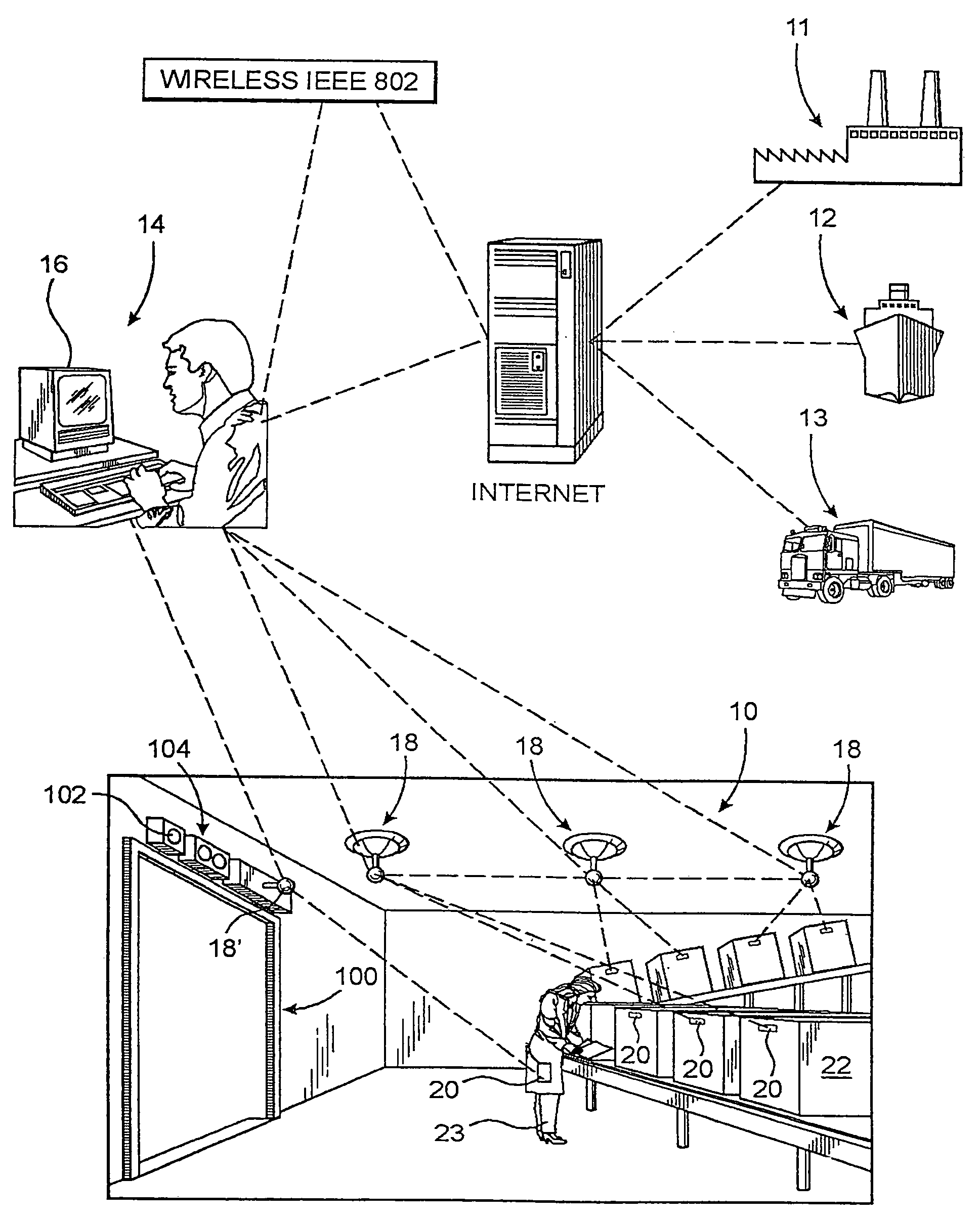
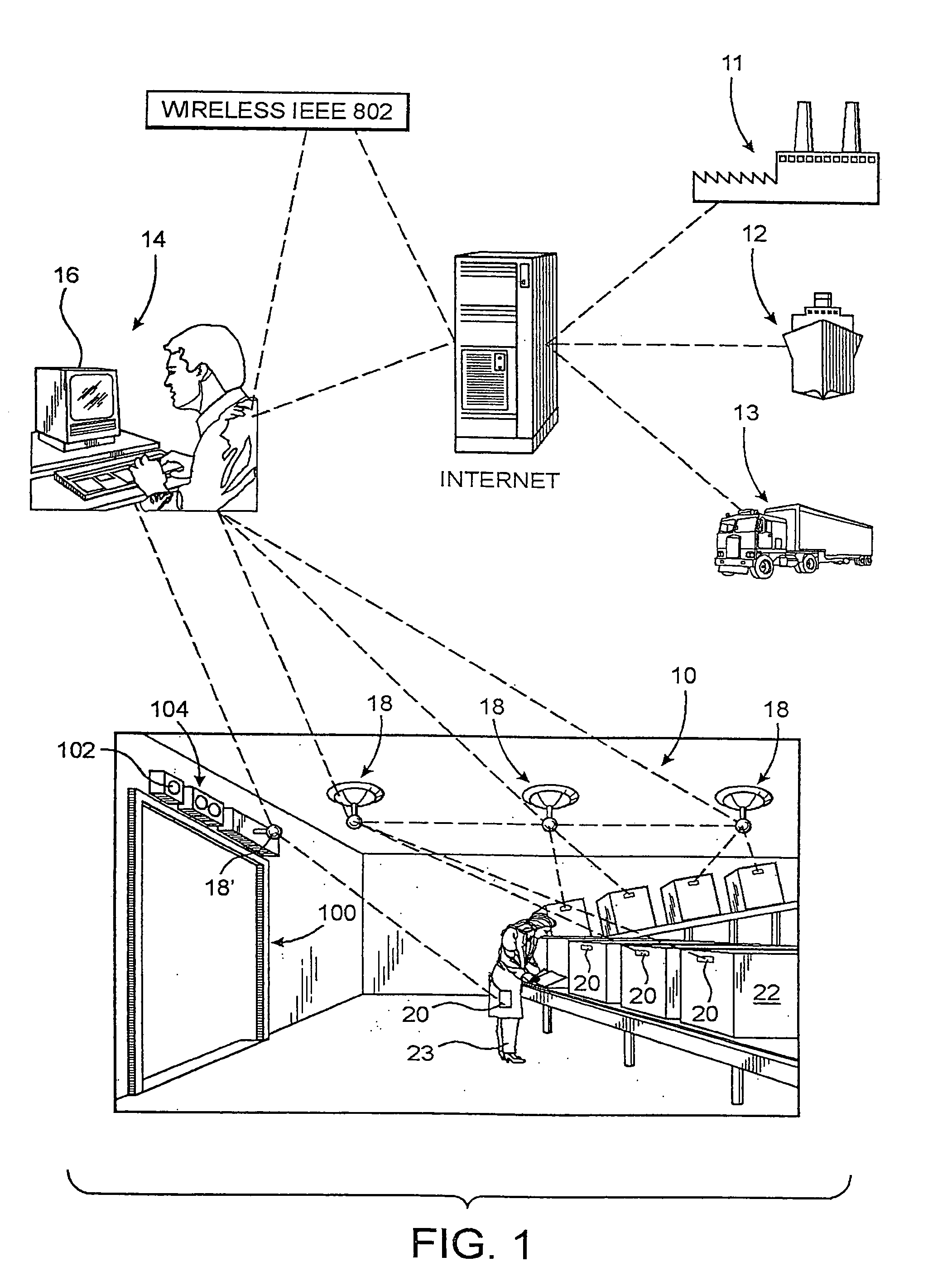
[0053]As shown in the accompanying Figures and as generally represented in FIG. 1, the present invention is directed to a real time total asset visibility system particularly, but not exclusively, adapted for maintaining effective inventory control as well as being capable of accomplishing efficient tracking of a plurality of articles or objects, including animate and inanimate objects, wherein the status of the various articles or objects can be determined on a real time basis. As used herein, the status of the various monitored articles is more specifically meant to describe the ability to determine the existence, location, identity, direction of movement, as well as the passage of the various articles to and from a monitored locale. However, at least one additional preferred embodiment is structured to also monitor the status of at least one predetermined characteristic of the object such as, but not limited to, temperature. The temperature status may be of particular importance ...


PUM


Abstract

A system and method for tracking articles and controlling inventory thereof on a real time basis comprising the use of a tag assembly including a plurality of tags including both active tags and passive tags distinguishable from one another by the provision of a self contained power source in the active tags. One or more readers are disposed within a locale being monitored and are structured to communicate received data transmission from a host controller, for additional administrative processing in terms of determining the existence, location and / or movement of various articles with which the plurality of tags are directly associated. Depending on their category the tags may be activated by either entering an electric field of a predetermined first frequency or by receiving an activation signal from the reader assembly also transmitted at the first predetermined frequency. Communication between the tags and the reader occurs at a second frequency being different from the first frequency.

Description

CLAIM OF PRIORITY[0001]The present application is a continuation-in-part application of patent application Ser. No. 10 / 253,254, filed Sep. 24, 2002, which has matured into U.S. Pat. No. 6,804,578 on Oct. 12, 2004, which is a continuation-in-part of patent application Ser. No. 09 / 976,734, filed Oct. 12, 2001, now U.S. Pat. No. 6,662,068, issued Dec. 9, 2003.BACKGROUND OF THE INVENTION[0002]1. Field of the Invention[0003]This invention is directed to a system which allows effective inventory control and extensive tracking capabilities of a plurality of articles by providing total real time access to a monitored locale in order to establish the existence, location and / or direction of movement of the articles. A plurality of tags are associated with the various articles being monitored, at least some of which include multi-frequency and uni-directional or multi-directional communication capabilities which at least partially serve to extend the operative range between the tags and a read...

Claims


Application Information

Patent Timeline
Patent Type & Authority Patents(United States)
IPC IPC(8): G06F19/00G01S19/14G01S19/34G05B19/00G06K17/00G06K19/07G06Q10/00
CPCG05B19/00G06K17/00G06K17/0022G06Q10/087G06Q10/06G06K19/0723G06K2017/0045
Inventor GHAFFARI, TOURAJ
Owner GHAFFARI TOURAJ
Why Eureka
Try Eureka