Low cost high speed electrical machine

a high-speed, electrical machine technology, applied in the direction of dynamo-electric machines, magnetic circuit rotating parts, magnetic circuit shapes/forms/constructions, etc., can solve the problems of reducing the potential power capability and efficiency of such a construction, hysteresis and eddy current losses in the lip could be very high, and the problem worse, so as to reduce the hoop stress in the lip, reduce the construction cost, and high power density

Inactive Publication Date: 2006-08-01
REVOLUTION ELECTRIC MOTOR
View PDF23 Cites 30 Cited by
  • Summary
  • Abstract
  • Description
  • Claims
  • Application Information

AI Technical Summary

Benefits of technology

[0008]Accordingly, the invention provides a brushless, axial gap, air core electrical machine that achieves exceptionally high power density with very low construction cost. The electrical machine has a rotor that comprises two discs, each having ferromagnetic portions, that are axially spaced apart to form an armature airgap. A stationary air core armature is located in the armature airgap with windings for providing power conversion. At least one of the two rotor discs comprises a circumferential array of multiple alternating axial polarity permanent magnet poles facing the armature airgap. The permanent magnet poles drive magnetic flux circumferentially through the ferromagnetic portions and axially through the armature airgap. The discs also comprise an integral axially extending circumferentially continuous lip outside of the permanent magnet poles that radially contains the poles. The lip has an integral shear connection with the disc that substantially reduces the hoop stress in the lip that would otherwise occur from the containment of the permanent magnet poles when rotated to high speed.

Problems solved by technology

Because the shear lip is constructed from metal such as steel, hysteresis and eddy current losses in the lip could be very high especially from high-speed operation.
The electrical conductivity of steel is also roughly five times higher than that of rare earth permanent magnets, which could make the problem worse.
Secondly, the lip also provides a path for magnetic flux leakage around magnets on a single rotor disk from the armature airgap side directly to the lip.
This would be considered to reduce the potential power capability and efficiency of such a construction.

Method used


Image

  • Low cost high speed electrical machine
  • Low cost high speed electrical machine
  • Low cost high speed electrical machine

Examples


Embodiment Construction

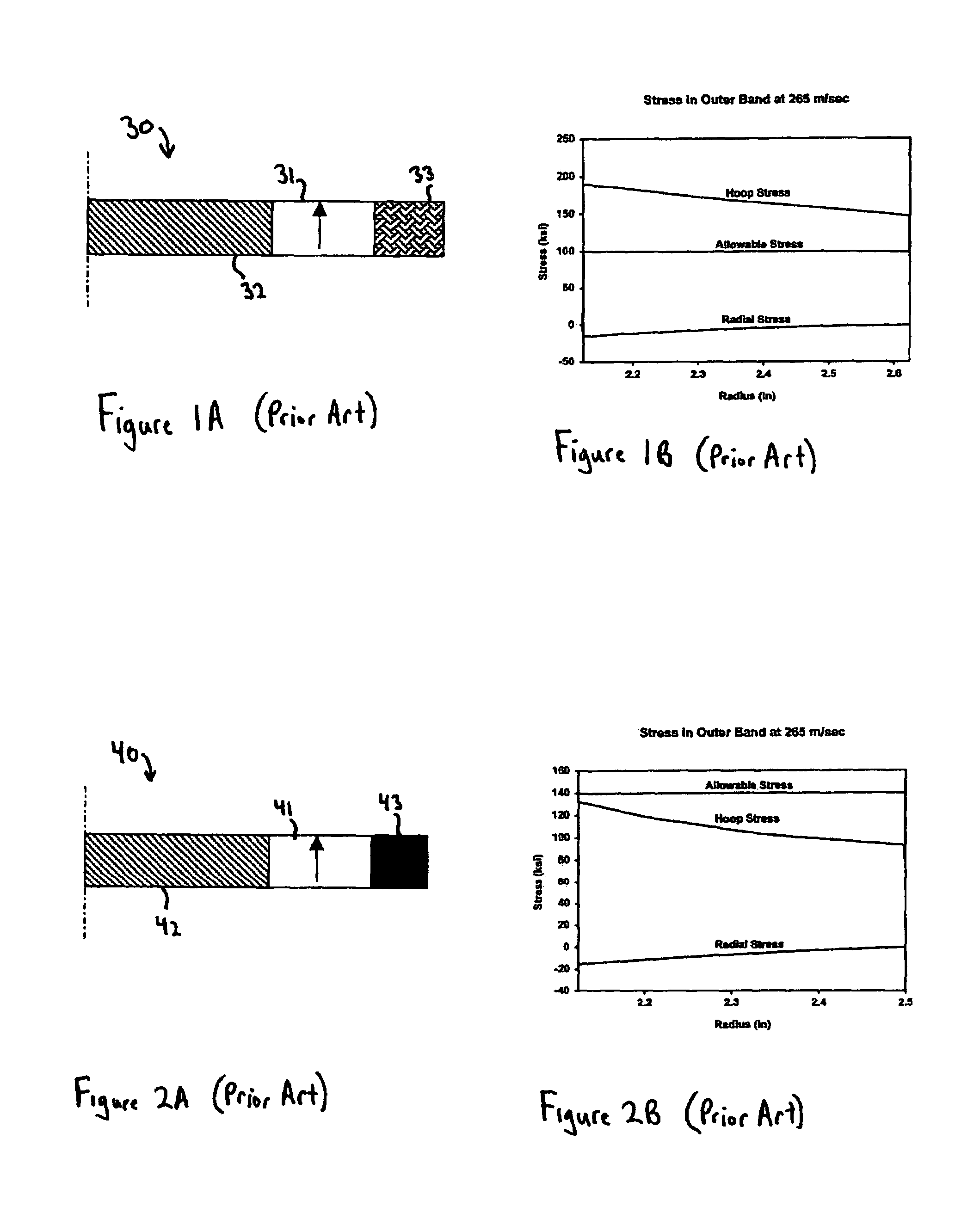
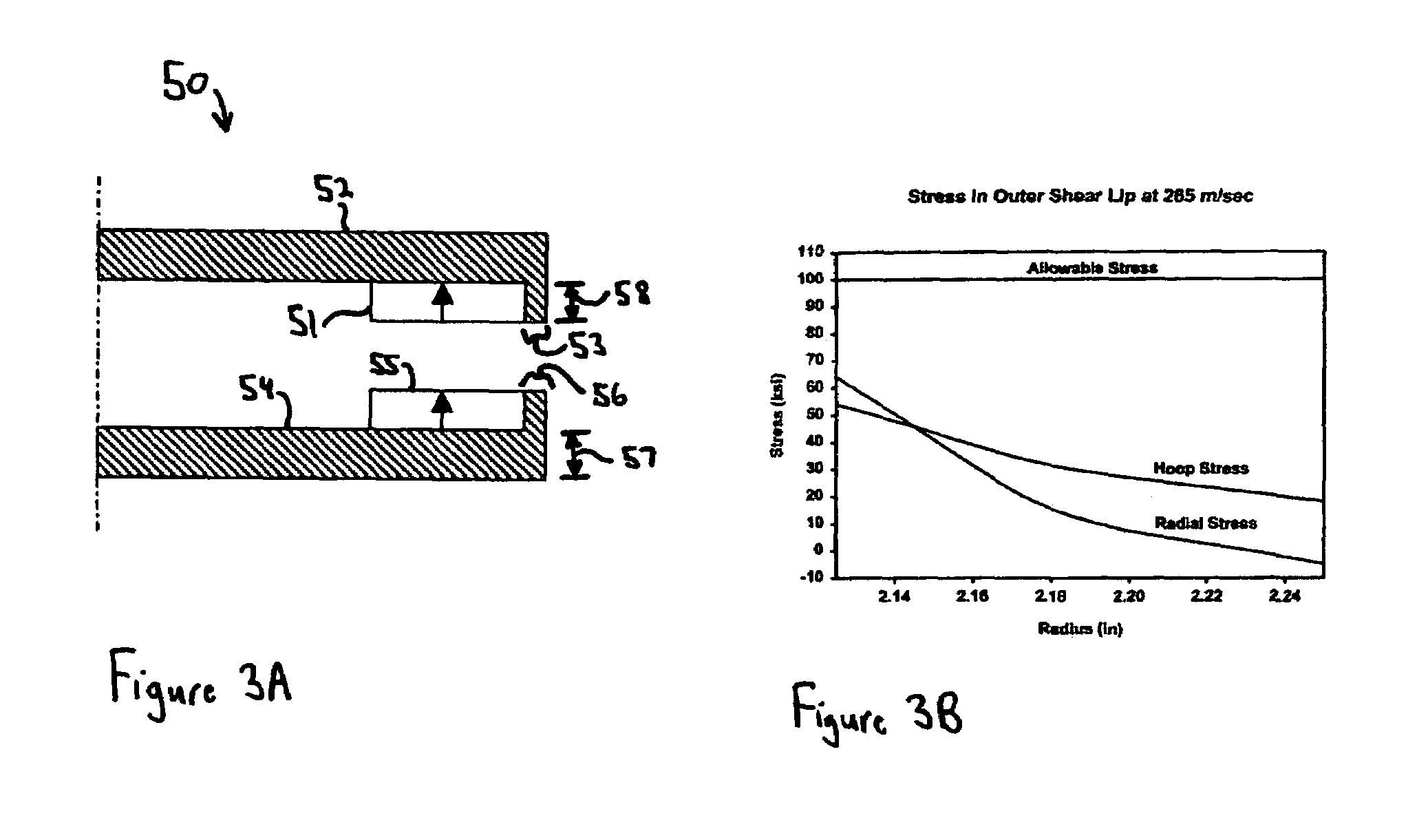
[0041]Turning to the drawings, wherein like reference characters designate identical or corresponding parts, a rotor 50 shown in FIG. 3A includes a circumferential array of alternating axial polarity permanent magnet poles 51 attached to a rotor disc 52 that has a shear lip 53 for containment of the magnet poles 51. The rotor 52 is preferably constructed from metal such as steel so that it possesses a high shear strength. The rotor 52 could be constructed from nonferrous metal, however ferromagnetic material would need to be placed axially behind the permanent magnets for circumferential conduction of the magnetic flux. The stresses in the lip 53 are shown in FIG. 3B. Unlike prior art band constructions, the radial stress is high and the hoop stress is simultaneously lowered. Both stresses are well below the allowable stress even when the rotor is rotated to a magnet peripheral speed of 265 m / sec. The steel rotor construction is also more durable and insensitive to temperature, unli...


PUM


Abstract

A high speed brushless axial gap air core electrical machine includes a rotor mounted for rotation about an axis, and a stationary stator that magnetically interacts with the rotor. The rotor has two discs that are axially spaced apart to form an armature airgap. A stationary air core armature, with windings made of multiple individually insulated strand conductor wire for providing energy conversion, is located in the armature airgap. At least one of the discs carries a circumferential array of multiple alternating axial polarity permanent magnet poles facing the armature airgap. The magnets drive magnetic flux circumferentially through ferromagnetic portions of the discs and axially through the armature airgap. The discs have an integral axially extending circumferentially continuous lip outside of the array of magnet poles. The lip has a integral shear connection with the disc that substantially reduces the hoop stress in the lip that would otherwise occur from the radial containment of the magnet poles when rotated to high speed.

Description

[0001]This is related to U.S. Provisional Application No. 60 / 486,776 filed on Jul. 11, 2003.[0002]This invention pertains to electrical machines for converting between electrical and mechanical energy and more importantly to a brushless, axial gap, air core electrical machine that provides exceptionally high power density with very low construction cost.BACKGROUND OF THE INVENTION[0003]There is a desire for low cost electrical machines for converting between electrical and mechanical energy that have both high efficiency and high performance capability. Unfortunately, current devices tend to suffer from one of more of a number of deficiencies that include low efficiency, low power density, and complex and expensive constructions.[0004]Conventional permanent magnet radial gap motor / generators utilize a rotor with banded permanent magnets that is surrounded by a laminated stator. The rotor has a limited magnet peripheral speed and hence the power capability per amount of magnet and to...

Claims


Application Information

Patent Timeline
Patent Type & Authority Patents(United States)
IPC IPC(8): H02K1/00
CPCH02K1/2793H02K21/24H02K3/47H02K1/2798
Inventor GABRYS, CHRISTOPHER W.
Owner REVOLUTION ELECTRIC MOTOR
Why Eureka
Try Eureka