
Temperature control system

a temperature control system and temperature control technology, applied in the field of information processing systems, can solve the problems of uneven temperature profiles in the vehicle, and insufficient temperature control system

Inactive Publication Date: 2006-08-01
INT BUSINESS MASCH CORP
View PDF19 Cites 61 Cited by
  • Summary
  • Abstract
  • Description
  • Claims
  • Application Information

AI Technical Summary

Problems solved by technology

Currently, temperature control systems, while found to be generally satisfactory in most situations, are not sufficient for many environments where ambient temperatures are quite variable and difficult to control.
This situation creates uneven temperature profiles throughout the vehicle where some of the occupants are at a comfortable temperature and others are either too hot or too cold.
The problem becomes worse when the vehicle changes directions and begins to travel in another direction in which the suns rays enter the vehicle from another direction and further adjustments to the air-conditioning or heating system need to be made.
While this may provide some control over general area temperatures of the vehicle, it does not address the above noted sun-ray heating problem and it is only marginally effective even for specific vehicle area heating since there is generally a great deal of spontaneous mixing with the amorphous and continuous air volume within the vehicle.
The temperature control problem is present on hot days when air-conditioning systems are required to cool the air, and also on cold days when heating system control is required to heat the air inside the vehicle.
This activity is an endless cycle and is quite distracting especially to a driver who is usually the person most familiar with the temperature control devices for the vehicle.
Another more serious and even life-threatening problem with current temperature control systems occurs when a vehicle is parked or disabled with infants inside the vehicle.
When the vehicle heats up internally to a temperature which is life-threatening, there is no way to counter-act the heating effect of a parked vehicle unless someone is present to turn-on the air-conditioning system.
The same is true for vehicles which are disabled and exposed to extremely cold temperatures for extended periods of time.

Method used


Image

  • Temperature control system
  • Temperature control system
  • Temperature control system

Examples


Embodiment Construction

[0018]It is noted that circuits and devices which are shown in block form in the drawings are generally known to those skilled in the art, and are not specified to any greater extent than that considered necessary as illustrated, for the understanding and appreciation of the underlying concepts of the present invention and in order not to obfuscate or distract from the teachings of the present invention. Although the present invention is herein disclosed in a motor vehicle example, it is understood that the invention applies as well to any environment in which it is desirable to control temperature conditions at various points within a designated air space.

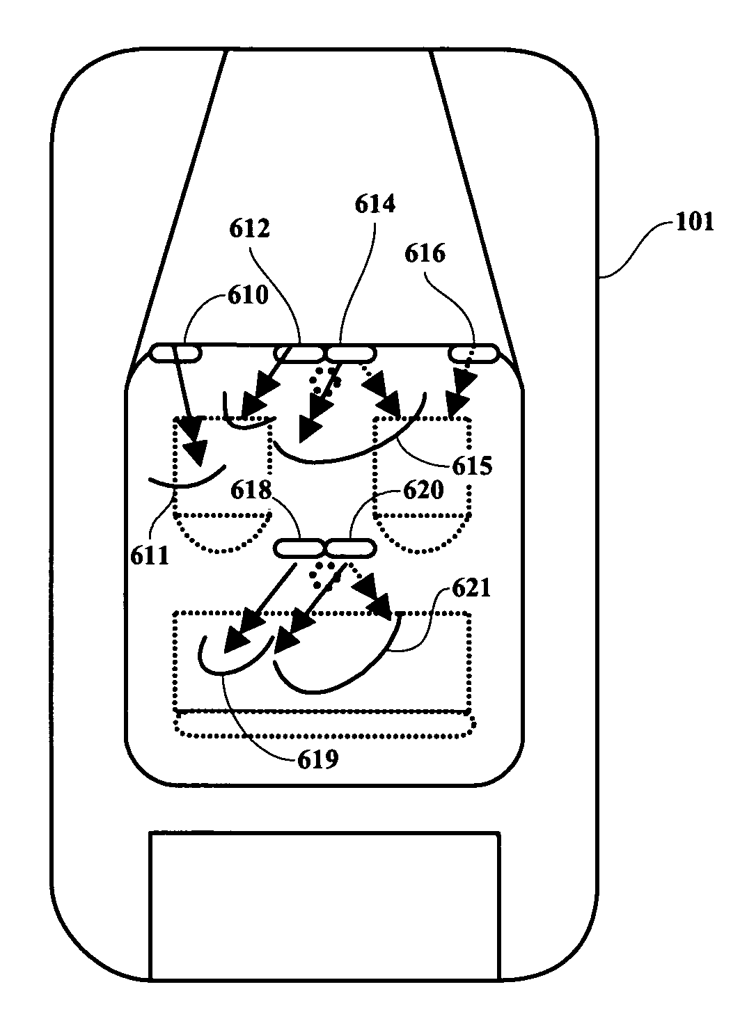
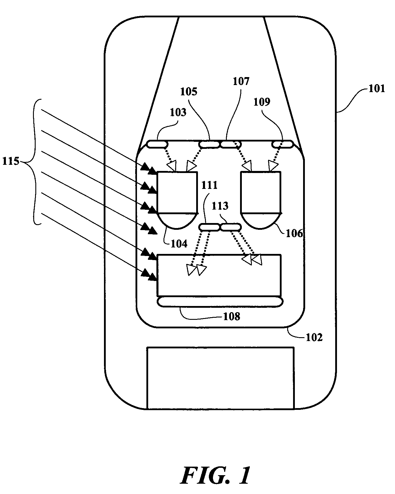
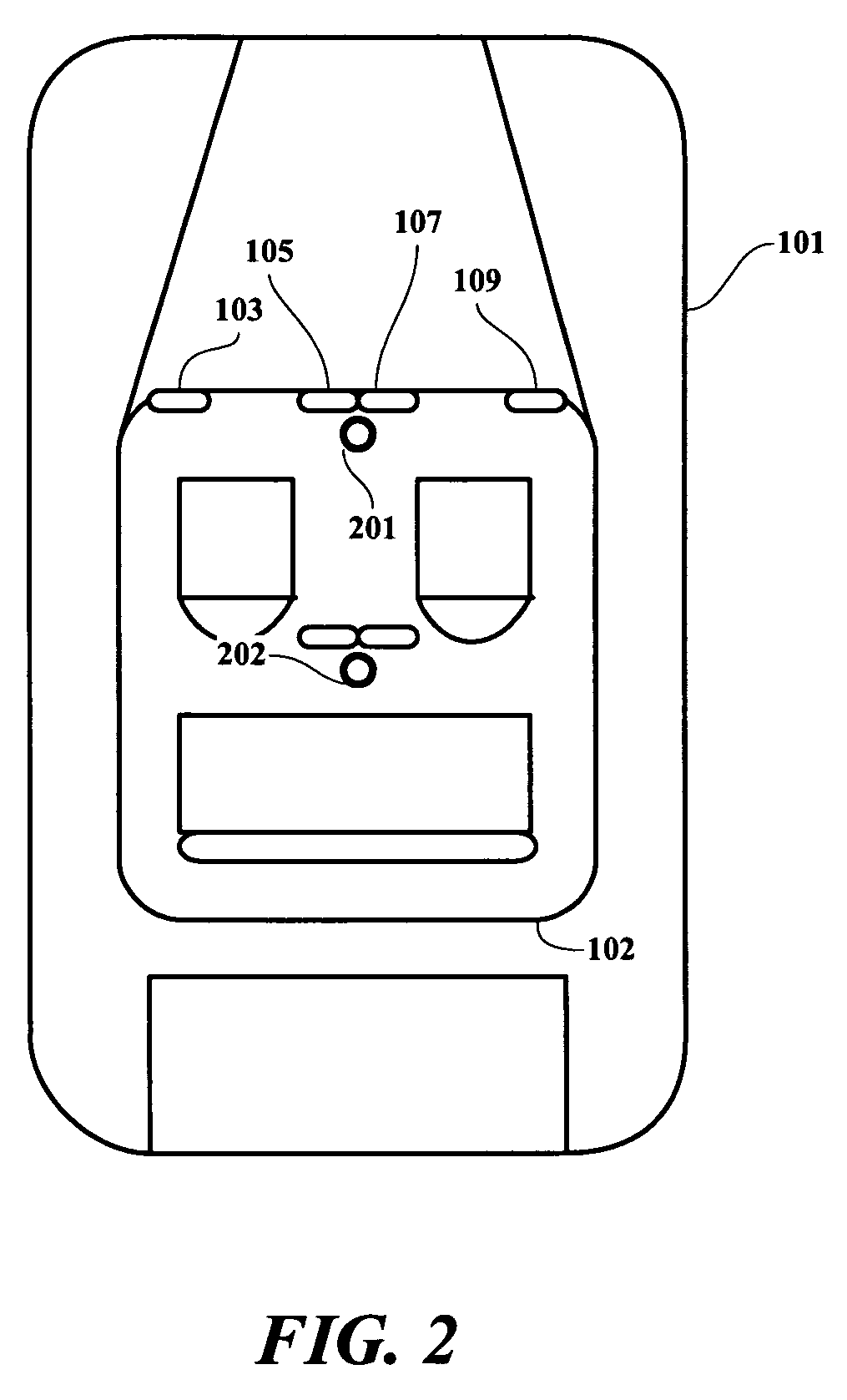
[0019]In an exemplary embodiment of the present invention, heat sensors such as infrared cameras are coupled to processing circuitry to control air vents and fans to provide tailored temperature balancing in a dynamically changing environment and to prevent and / or initiate alarm systems when an extreme temperature condition is det...


PUM

PropertyMeasurementUnit
temperatureaaaaaaaaaa
temperaturesaaaaaaaaaa
infrared temperature sensingaaaaaaaaaa

Abstract

A method and implementing computerized system are provided for enabling point-specific temperature control for a given airspace. In an exemplary embodiment, infrared sensing devices are positioned in a vehicle to sense and record temperatures at various points within the vehicle airspace. This temperature profile is mapped relative to points within the vehicle and compared to a preferred temperature database to provide temperature control signals. The temperature control signals are, in turn, applied to temperature control air vent devices which are effective to direct appropriate air flows to specific areas such that actual measured temperatures at control points in the vehicle airspace approach the preferred temperatures for the respective control points. In another example, when sensed temperatures are above or below predetermined emergency condition limits for a predetermined period of time, various alarm systems are activated until the sensed emergency condition is corrected.

Description

FIELD OF THE INVENTION[0001]The present invention relates generally to information processing systems and more particularly to a methodology and implementation for enabling automatic control of variable temperature profiles and related alarm systems.BACKGROUND OF THE INVENTION[0002]Currently, temperature control systems, while found to be generally satisfactory in most situations, are not sufficient for many environments where ambient temperatures are quite variable and difficult to control. For example, when a motor vehicle is speeding along a long stretch of highway on a sunny day, the sun rays enter the vehicle from only one angle while the vehicle continues to travel in the same direction. Occupants of the vehicle on the side of the vehicle where the suns rays are entering tend to be hotter than occupants on the other side of the vehicle, and those on the sun side of the vehicle tend to be hotter on the side of their body adjacent to the window compared to the inside of the vehi...

Claims


Application Information

Patent Timeline
Patent Type & Authority Patents(United States)
IPC IPC(8): G08B17/00B60H1/00F24F11/00G01K13/02G05D23/19
CPCB60H1/00742F24F11/0012G05D23/1931G01K13/02G01K2201/02F24F11/30F24F2110/10
Inventor MARTINEZ, ANTHONY EDWARD
Owner INT BUSINESS MASCH CORP
Learn More