Electric dental cleaning device

a cleaning device and electric technology, applied in the direction of brushes, vehicle maintenance, sport apparatus, etc., can solve the problems of inability to inadvertently prematurely discharge storage batteries, etc., and achieve the effects of facilitating the reading of encoding, enhancing user comfort, and gentle cleaning operation

Inactive Publication Date: 2006-08-08
BRAUN GMBH
View PDF96 Cites 147 Cited by
  • Summary
  • Abstract
  • Description
  • Claims
  • Application Information

AI Technical Summary

Benefits of technology

[0033]The encoding device or interlock canceling element is preferably constructed as a separate component suitable for detachment from the remaining part of the cleaning tool or for replacement. This affords the advantage of requiring only a single mold for the manufacture of the cleaning tool. By mounting the separate encoding device the cleaning tools are encoded on an individual basis and assignable to a handle section of a particular type. However, the encoding device constructed as interlock canceling element may also be integrated in the cleaning tool when it is desirable to implement merely the function of a safety interlock preventing switching on of the appliance on travels or in combination with incompatible cleaning tools.
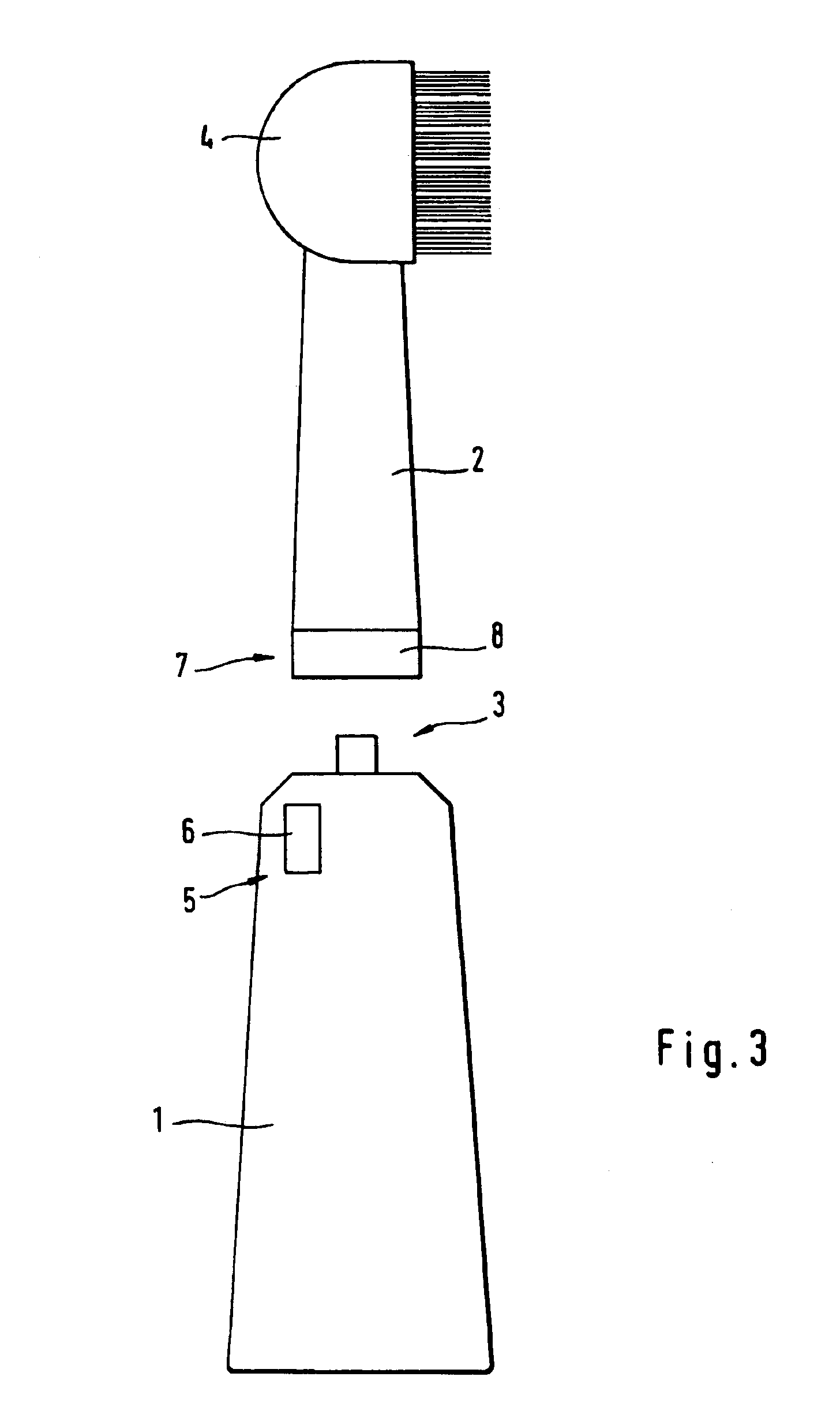
[0034]The encoding device is arranged preferably in the area of the connection or coupling between the cleaning tool and the handle section. This facilitates the reading of the encoding, meaning the detection of the interlock canceling element by the recognition device on the handle section. In particular the encoding device may be integrated in a ring arranged at the end of the cleaning tool close to the handle section, being in particular snap-fittable thereto by positive engagement therewith. The various configurations of the recognition devices may be provided singularly or in combination. The same applies to the various configurations of the encoding device on the cleaning tool.
[0035]Apart from protecting the handle section against inadvertent turning on and improper use of incompatible cleaning tools, an encoding of the cleaning tools and its detection by the handle section may be utilized to advantage for implementing further functions. In a further aspect of the invention the handle section may control one or preferably several functions of the dental cleaning device in dependence upon the respective cleaning tool detected. Assuming that each user of the handle section has his or her own cleaning tool, particularly the control device o

Problems solved by technology

Any inadvertent premature discharge of a

Method used


Image

  • Electric dental cleaning device
  • Electric dental cleaning device
  • Electric dental cleaning device

Examples


Embodiment Construction

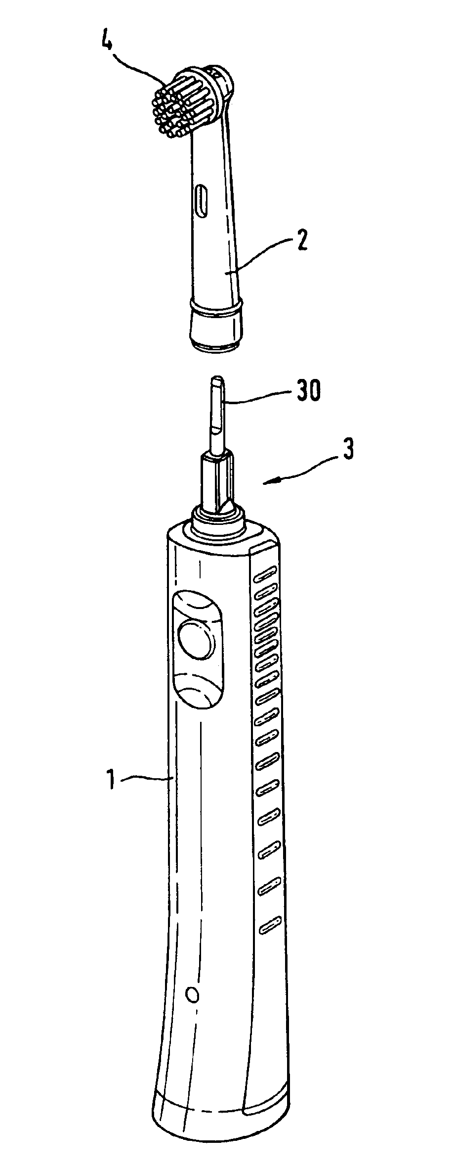
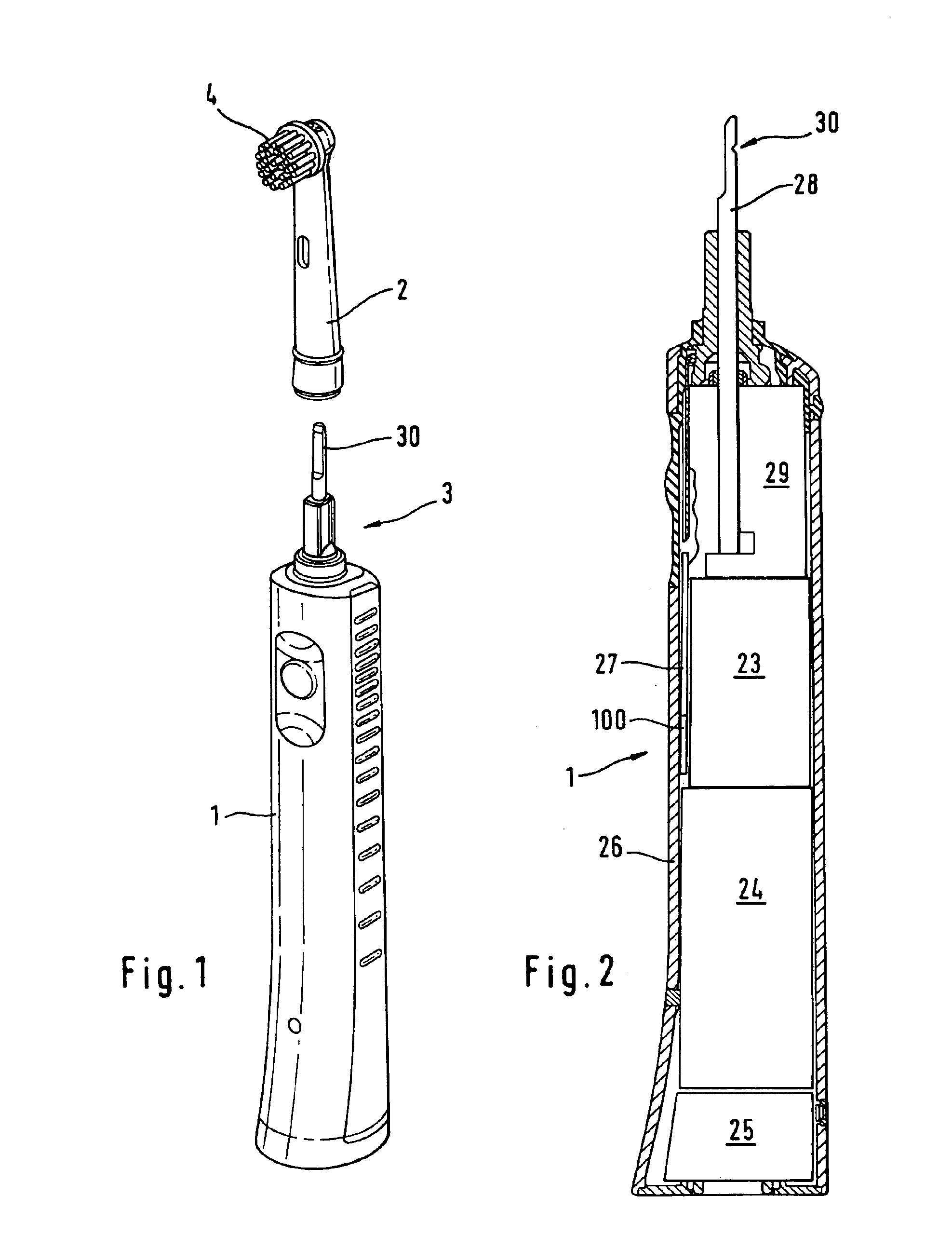
[0076]The electric toothbrush shown in the Figures has a handle section 1 with a closed housing 26 accommodating, among other components and as illustrated in FIG. 2, in a manner known in the art an electric motor 23, a storage battery 24 adapted to be coupled to a charging station through a charging module 25 disposed at the bottom, and a control device 27 which may possess a printed circuit board or microprocessor. Various brush attachments 2 are seatable upon the end of the handle section 1 to function as brushing or cleaning tools. By means of a coupling device 3 the brush attachment 2 can be mechanically coupled to the handle section 1 in order to transmit the driving motion of the electric motor to the brush head 4 of the brush attachment 2. The coupling device 3 which may be made of one or several parts or pieces comprises a positive- or frictional-engagement element for positioning the cleaning tool body in its proper location and, in addition, a drive coupling which transmi...


PUM


Abstract

The invention is directed to a dental cleaning device. It relates in particular to a handle section of an electric toothbrushing device, with a coupling section for coupling various cleaning tools thereto, a drive mechanism for driving the coupled cleaning tool, and a control device for controlling the drive mechanism. The invention further relates to such cleaning tools. According to the invention the handle section includes an electronic interlock device which is deactivated by an encoded interlock canceling element on the cleaning tool only when the cleaning tool is coupled to the handle section (FIG. 4).

Description

FIELD OF THE INVENTION[0001]This invention relates to an electric dental cleaning device. The invention relates in particular to the handle section of such a dental cleaning device which has at least one or several coupling sections for the coupling of various cleaning tools, a drive mechanism for driving the coupled cleaning tool, and a control device. Finally the invention relates to the cleaning tools, particularly brush attachments for such a handle section.BACKGROUND OF THE INVENTION[0002]Dental cleaning devices such as electric toothbrushes or electric oral irrigators customarily have a grip or a handle section or handhold to which a variety of cleaning tools such as brush attachments, jet nozzles, interproximal brushes are attachable, thus enabling several users to use the dental cleaning device with their own, in particular person-related cleaning tools. Such electric toothbrushes are known, for example, from DE 19627752 A1 or EP 0624079 B1.[0003]From DE 299 15 858 U1 a dent...

Claims


Application Information

Patent Timeline
IPC IPC(8): A61C17/22A61C1/00A61C1/18
CPCA61C17/222A61C17/221A61C1/0015A61C1/18
Inventor HILSCHER, ALEXANDERREICK, HANSJORGSCHWARZ-HARTMANN, ARMINTRAWINSKI, PETERSTRATMANN, MARTINVORBECK, WOLFGANG
Owner BRAUN GMBH
Why Eureka
Try Eureka