
Spark plug and ignition apparatus using same

a technology of spark plugs and ignition devices, which is applied in the direction of spark plugs, mechanical devices, machines/engines, etc., can solve the problems of long time-consuming and laborious, inability to provide information about how to reduce such poor wear performance, and the relationship between the conformation of electrodes and a necessary amount of ignition energy, etc., to achieve the effect of lowering the ignition energy and saving the energy consumed by the ignition apparatus

Inactive Publication Date: 2006-08-08
DENSO CORP +1
View PDF29 Cites 7 Cited by
  • Summary
  • Abstract
  • Description
  • Claims
  • Application Information

AI Technical Summary

Benefits of technology

The present invention provides a spark plug with a reduced amount of energy required for ignition, which can save energy and reduce wear of the electrodes. The invention achieves this by regulating the conformations of the electrodes to lower the amount of cooling energy at the electrodes. The invention also provides an ignition apparatus with the spark plug, which can secure a steady ignitability and reduce wear of the electrodes. The study conducted by the inventors showed that a spark plug with a reduced amount of energy required for ignition can be achieved by reducing the diameters of the electrodes and the spacing between them. The invention provides different configurations for the spark plug and the ignition apparatus, which can be adapted based on the desired power-saving and ignitability requirements.

Problems solved by technology

However, the relationship between the conformations of the electrodes and a necessary amount of the ignition energy has not been solved yet, and how to decide the ignition energy in designing a spark plug of which electrodes are made compact has long been unknown.
However, the foregoing publication does not provide any information about how to reduce such poor wear performance.

Method used


Image

  • Spark plug and ignition apparatus using same
  • Spark plug and ignition apparatus using same
  • Spark plug and ignition apparatus using same

Examples


Embodiment Construction

[0068]Referring to the accompanying drawings, preferred embodiments of the present invention will now be described.

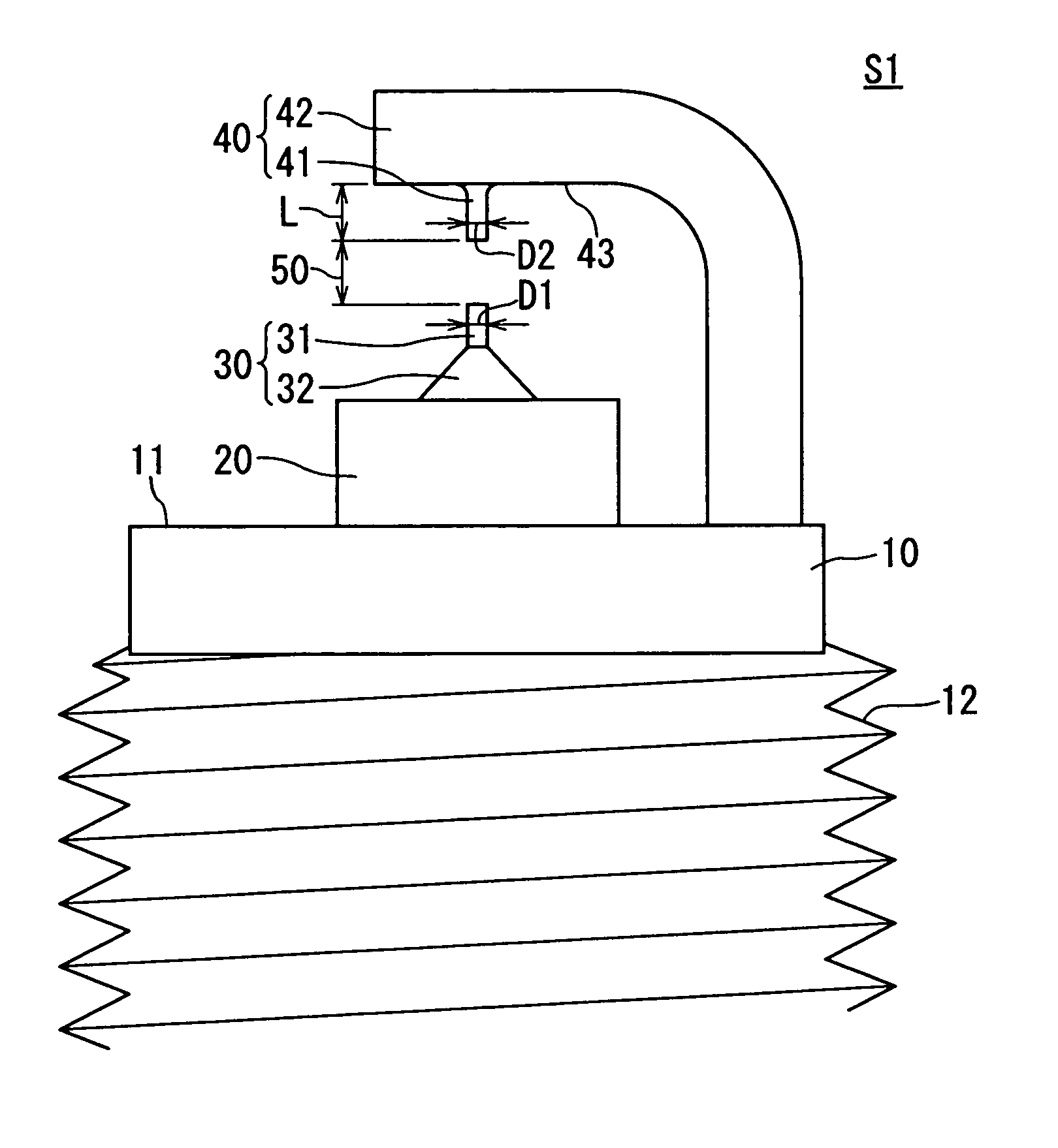
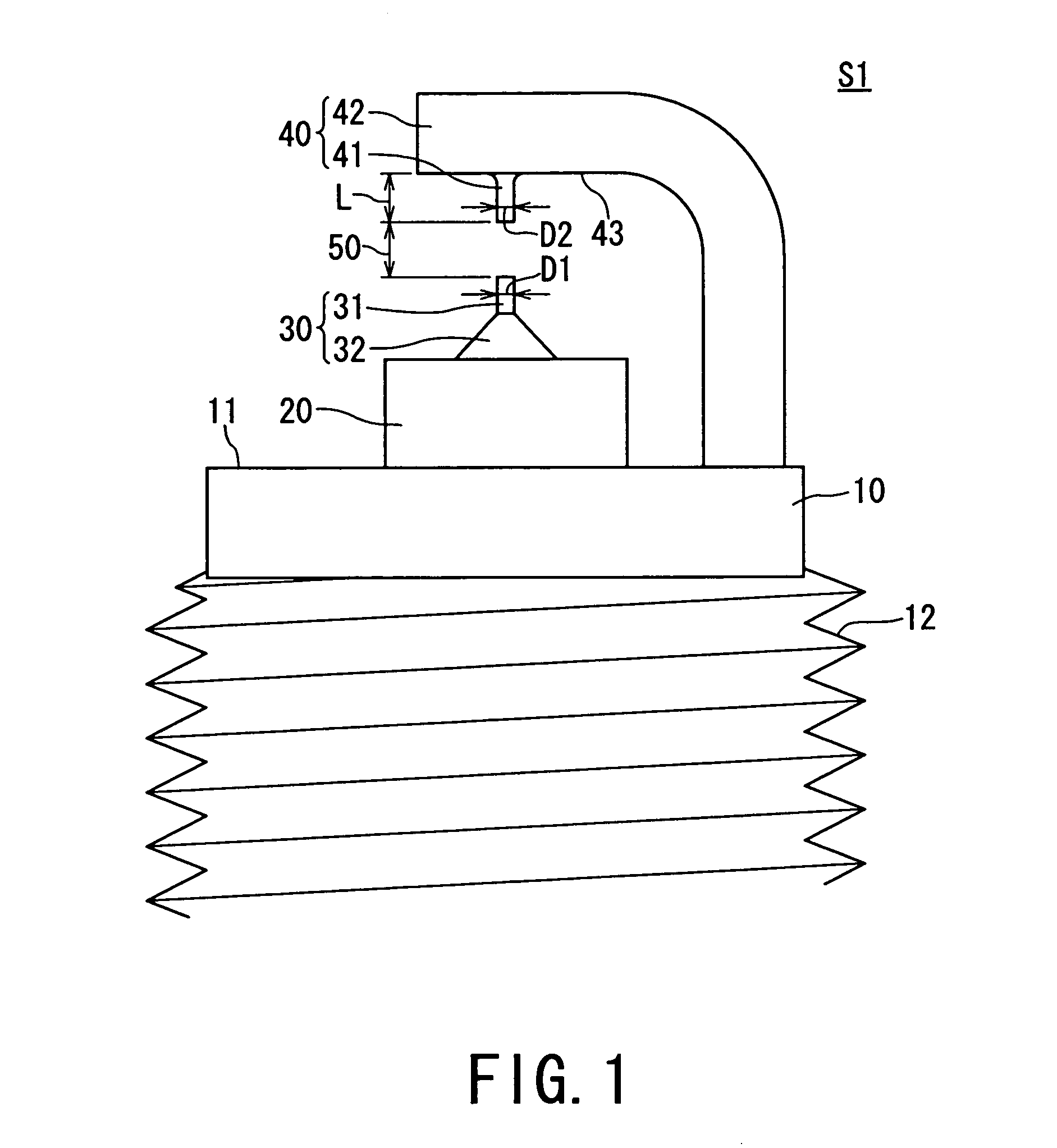
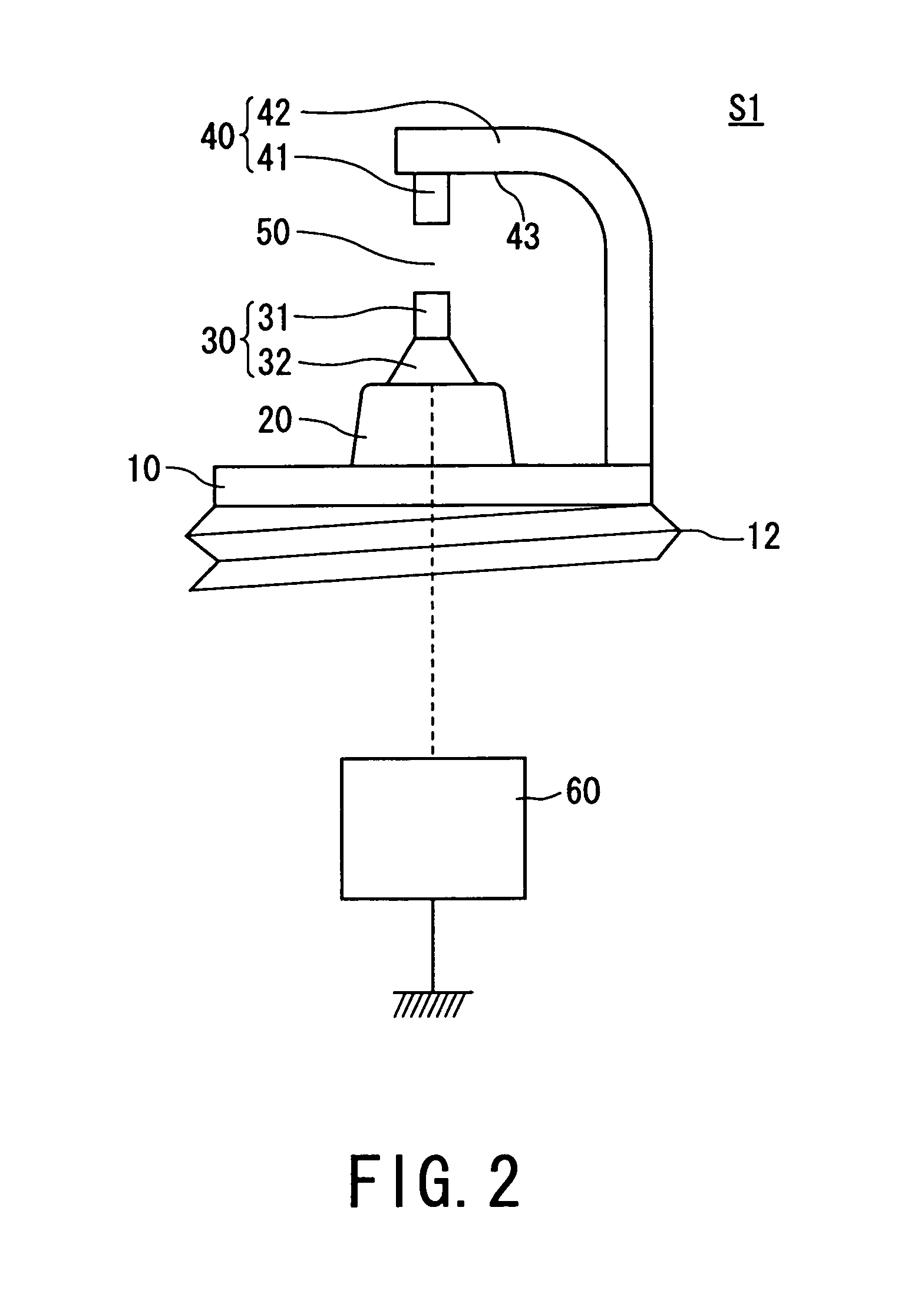
[0069]Referring to FIGS. 1 to 8 and 11 to 13, one embodiment of the present invention will now be described. FIG. 1 partially shows the configuration of a spark plug S1, but only an essential part thereof, according to the first embodiment. The spark plug S1 has a mounting bracket 10, which can be attached to an automobile engine (not shown) employed as an internal combustion engine. The mounting bracket 10 is made of carbon steel and manufactured into a cylindrical form through various types of working, such as cold forging and cutting working.

[0070]FIG. 1 shows one end of the mounting bracket 10. On the outer circumferential surface of the mounting bracket 10 is formed a mounting threaded part 12 for thread-fastening the spark plug to a mounting hole of the engine. The thread diameter of the mounting threaded part 12 can be formed as being a size of M12 or less.

[0071]...


PUM


Abstract

A power-saving type of ignition apparatus is provided with a spark plug of which electrodes (30, 40) are regulated in their shapes to lower an amount of energy required for its ignition. To face to a tip (31) of a center electrode (30) extending from a mounting bracket (10), a cylindrical protrusion (41) is built on one surface (43) of an earth electrode (40). The protrusion extends toward the center electrode to form a discharge gap (50) between the protrusion and the tip of the center electrode. Both of the tip of the center electrode and the protrusion of the earth electrode are 2.3 [mm] or less in each diameter (D1, D2), thus an amount of energy required for ignition being limited to 17 [mJ] or less.

Description

[0001]This application is a division of Application No. 10 / 073,255, filed Feb. 13, 2002, the entire contents of which is hereby incorporated by reference in this application.BACKGROUND OF THE INVENTION[0002]The present invention relates to a spark plug and an ignition apparatus using the same.[0003]There is a variety types of spark plugs to ignite an engine. FIG. 11 shows one type of conventionally used ordinary spark plug. This spark plug is provided with a mounting bracket 10, a cylindrical center electrode 30 mounted on the mounting bracket 10, and a prismatic earth electrode 40 fixedly coupled with the mounting bracket 10. The center electrode 30 has one end 31 formed into a cylinder and extends from one end 11 of the mounting bracket 10, the one end 31 being insulation-supported within the mounting bracket 10 from an insulating glass member 20 intervening therebetween. The earth electrode 40 has one end secured to the one end 11 of the mounting bracket 10 and the other end exte...

Claims


Application Information

Patent Timeline
Patent Type & Authority Patents(United States)
IPC IPC(8): F02P1/00H01T13/20F02P13/00H01T13/32H01T13/39H01T13/40
CPCH01T13/20H01T13/39H01T13/32
Inventor MIWA, TETSUYAYOSHINAGA, TOHRUKANAO, KEIJIOKABE, SHINICHI
Owner DENSO CORP
Learn More