

Injection cartridge filling apparatus
- Summary
- Abstract
- Description
- Claims
- Application Information
AI Technical Summary
Benefits of technology
Problems solved by technology
Method used
Image

Examples
Embodiment Construction
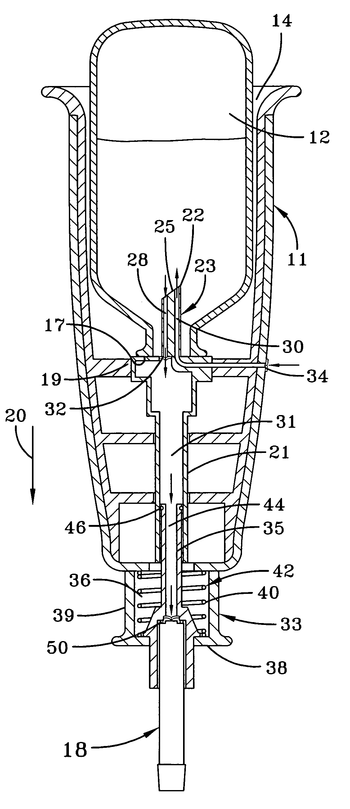
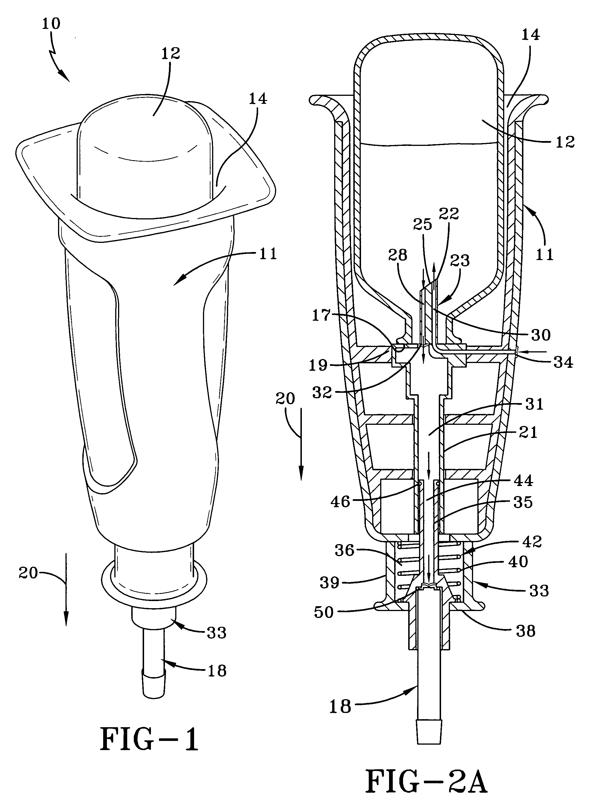
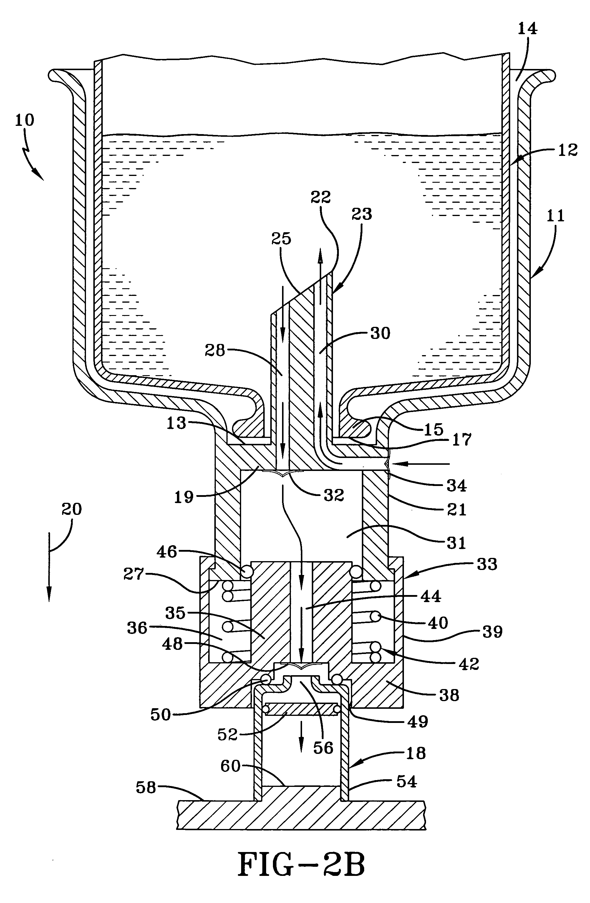
[0036]The invention involves a system for filling cartridges with fluid from a container by creating an air pressure differential across fluid in the container, where the container can be a non-collapsible container having a septum for closing a discharge orifice or a collapsible container such as a syringe with a piston which can be used to discharge fluid from the syringe. The inventive system includes a holder for holding the container, and an air pressure differential apparatus having walls defining a variable size chamber which is connected to the container. The walls are movable to expand or decrease the size of the chamber. When the chamber is in one of its expanded or decreased sizes (depending on the embodiment), fluid is drawn from the container—and when the chamber is moved to its other sizes, fluid is transferred into a cartridge. In one embodiment, a variable size chamber both forces air into the container and receives fluid from the container, from whence it is transfe...
PUM
| Property | Measurement | Unit |
|---|---|---|
| Force | aaaaa | aaaaa |
| Pressure | aaaaa | aaaaa |
| Flow rate | aaaaa | aaaaa |
Abstract
Description
Claims
Application Information