Rear projection type projector and its method of use

a projector and projector technology, applied in the field of rear projection type projectors, can solve the problems of equipment size growth, projection distance stretched, and reduction in the efficiency of light utilization in an effective rang

Inactive Publication Date: 2006-08-08
SEIKO EPSON CORP
View PDF5 Cites 6 Cited by
  • Summary
  • Abstract
  • Description
  • Claims
  • Application Information

AI Technical Summary

Benefits of technology

[0015]This enables an image projected to the screen projection surface to be extended in a slant direction. Consequently, an aspect ratio of the screen projection surface (equivalent to the actual projection range) is not limited by an aspect ratio of a liquid crystal panel, and it is possible to project an image limited to a range smaller than a range of housing the screen projection surface. Consequently, the invalid projection range decreases to enhance the utilization efficiency of light, thereby making it possible to improve illuminance of a projected image or reducing capacity of lighting means. Further, because a scale factor of projection decreases, a light path is shortened and the equipment becomes small-sized.

Problems solved by technology

Hence, there was a problem of a reduction in efficiency of light utilization in an actually effective range.
Namely, there was a problem that as an image was expanded excessively, the projection distance stretched and the equipment grew in size.
Further, because a scale factor of projection decreases, a light path is shortened and the equipment becomes small-sized.
Furthermore, since the light path of the projection light refracts in a V shape, the equipment becomes small-sized.

Method used


Image

  • Rear projection type projector and its method of use
  • Rear projection type projector and its method of use
  • Rear projection type projector and its method of use

Examples


Embodiment Construction

[0029]Rear Projection Type Projector

[0030]Referring to the drawings, an embodiment of this invention will be described below. Now, in each drawing, like reference characters designate like or corresponding objects, and part of the description will be omitted.

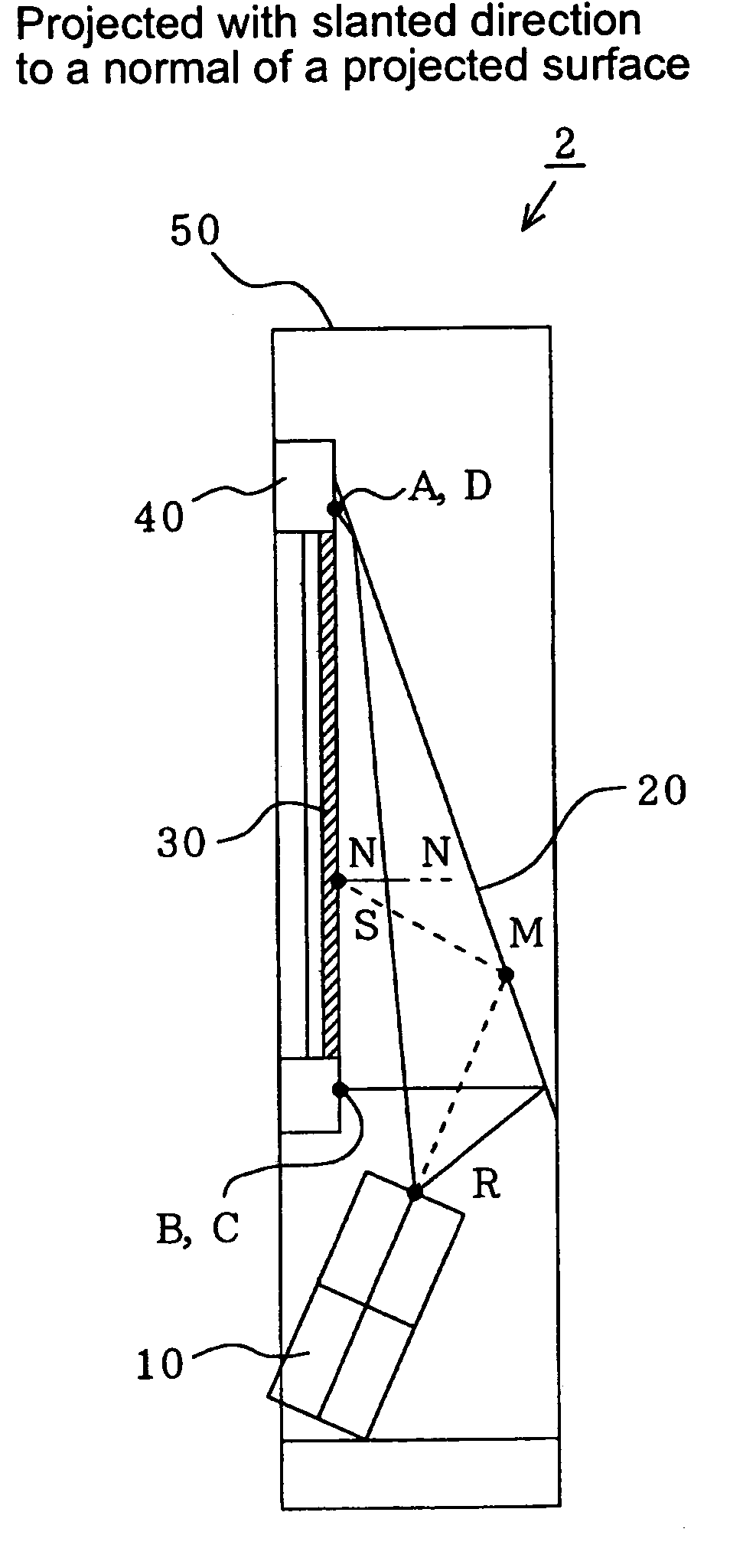
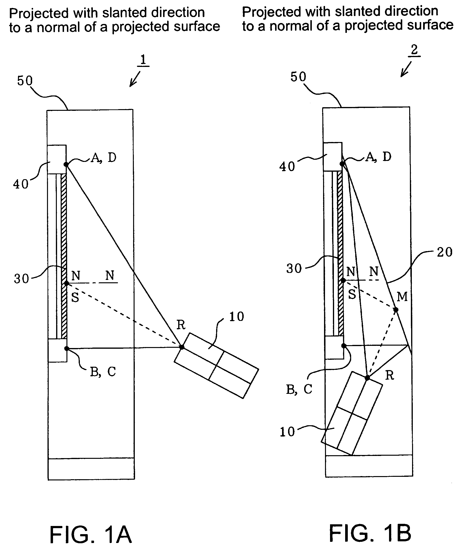
[0031]FIGS. 1(a) and (b) are schematic sectional views of a rear projection type projector according to an embodiment of this invention, wherein FIG. 1(a) shows a case of direct projection and FIG. 1(b) shows a case of projection by way of a reflector.

[0032]In FIG. 1(a), a projection direction of a projection unit 10 of a rear projection projector 1 is slanted relative to a screen projection surface 30. Namely, an optic axis R-S of projection light to be projected (shown in a dotted line therein) is slanted at a prescribed angle relative to a normal N-N of the screen projection surface 30. The prescribed angle (hereinafter referred to as an “oblique angle”) is an angle which makes the aspect ratio of the actual projection range ...


PUM

PropertyMeasurementUnit
shapeaaaaaaaaaa
widthaaaaaaaaaa
angleaaaaaaaaaa

Abstract

A rear projection type projector is provided. An optic axis of modulated light to be projected to a screen projection surface is slanted to a normal N-N of the screen projection surface and projected to a trapezoidal range ABCD housing the actual projection range EFGH. A reflector is disposed in the rear of the screen projection surface, a projection unit projecting modulated light is placed on a side of the screen projection surface, and the modulated light is projected towards the rear, and then reflected at the reflector. Further, image information is corrected and a distortion-free image is projected.

Description

RELATED APPLICATIONS[0001]This application claims priority to Japanese Patent Application No. 2003-161652 filed Jun. 6, 2003 which is hereby expressly incorporated by reference herein in its entirety.BACKGROUND[0002]1. Field of the Invention[0003]This invention relates to a rear projection type projector and particularly to a rear projection type projector with projection light projected from the rear of a screen projection surface and its method of use.[0004]2. Description of the Related Art[0005]FIGS. 7(a) and (b) are schematic sectional views of a conventional rear projection type projector, particularly, as a rear projection type projector installed in a playing apparatus, wherein the configuration of FIG. 7(a) is for direct projection, and the configuration of FIG. 7(b) is for projection by way of a reflector.[0006]In FIG. 7(a), a rear projection type projector 5 has a projection unit 10 projecting projection light modulated according to image information and a screen projectio...

Claims


Application Information

Patent Timeline
Patent Type & Authority Patents(United States)
IPC IPC(8): G03B21/14G03B21/22G03B21/28G03B21/56H04N3/23G02F1/13G02B27/18G03B21/00G03B21/10H04N17/00
CPCH04N9/3185G03B21/14G03B21/147G03B21/28G03B21/10
Inventor YAMAKAWA, HIDEMASA
Owner SEIKO EPSON CORP
Why Eureka
Try Eureka