Two piece surface mount header assembly having a contact alignment member

a header assembly and alignment member technology, applied in the field of surface mount header assemblies, can solve the problems of high insertion force of plug assemblies into receptacle assemblies to form connector assemblies, difficult to achieve coplanarity with a large number of contact pins, and increase the incremental cost of solder paste per header assembly

Inactive Publication Date: 2006-08-08
TYCO ELECTRONICS LOGISTICS AG (CH)
View PDF16 Cites 46 Cited by
  • Summary
  • Abstract
  • Description
  • Claims
  • Application Information

AI Technical Summary

Benefits of technology

[0007]In accordance with an exemplary embodiment, a header assembly comprises an insulative contact housing having a plurality of walls defining an interior cavity and an insulative alignment housing having at least one alignment rib extending on an exterior surface thereof. The alignment housing is separately provided from and independently mounted to the contact housing. A plurality of contacts are included within the cavity and extend through one of the walls to an exterior of the contact housing wherein the contacts flex against the alignment housing and abut the alignment rib, thereby ensuring coplanarity of the contacts for surface mounting to a circuit board.

Problems solved by technology

The mating of a plug assembly into a receptacle assembly to form a connector assembly often involves a high insertion force.
In one automotive connector system, fifty two contacts are employed in one version of the header assembly, and the large number of contacts presents manufacturing and assembly challenges in fabricating the header assembly, as well as installation problems during surface mounting of the header assembly to the circuit board.
Achieving coplanarity with a large number of contact pins, however, is difficult due to manufacturing tolerances over a large number of contacts.
Over a large number of header assemblies, however, the incremental cost of the increased amount of solder paste per header assembly can be significant, and non-planarity of the pin contacts with respect to the plane of the circuit board may negatively affect the reliability of the header assembly.
Additional solder paste thickness can also cause solder bridging problems for other surface mount components on fine pitch or may require different stencils to be used.
Depending upon the degree of non-planarity of the solder tails, some of the contacts may be weakly connected or not connected to the circuit board at all, either of which is an undesirable and unacceptable result.
Furthermore, the high insertion forces during engagement and disengagement of the header assembly and the plug assembly may be detrimental to the soldered connections of the header assembly.
As such, the mechanical connection of the solder clips incur the brunt of mechanical strain as the header assembly is mated and unmated from a mating connector.
Tolerances in manufacturing the solder clips, however, introduce additional non-planarity issues when the header assembly is soldered to a circuit board.
At one end of the tolerance range, the solder clips may prevent the contacts from fully contacting the circuit board, which may impair the quality of the soldered connections of the contacts.
At the other end of the tolerance range, the solder clips may not fully contact the circuit board during soldering, which may impair the ability of the solder clips to spare the contacts from large insertion and extraction forces as the header assembly is engaged and disengaged from a mating connector.

Method used


Image

  • Two piece surface mount header assembly having a contact alignment member
  • Two piece surface mount header assembly having a contact alignment member
  • Two piece surface mount header assembly having a contact alignment member

Examples


Embodiment Construction

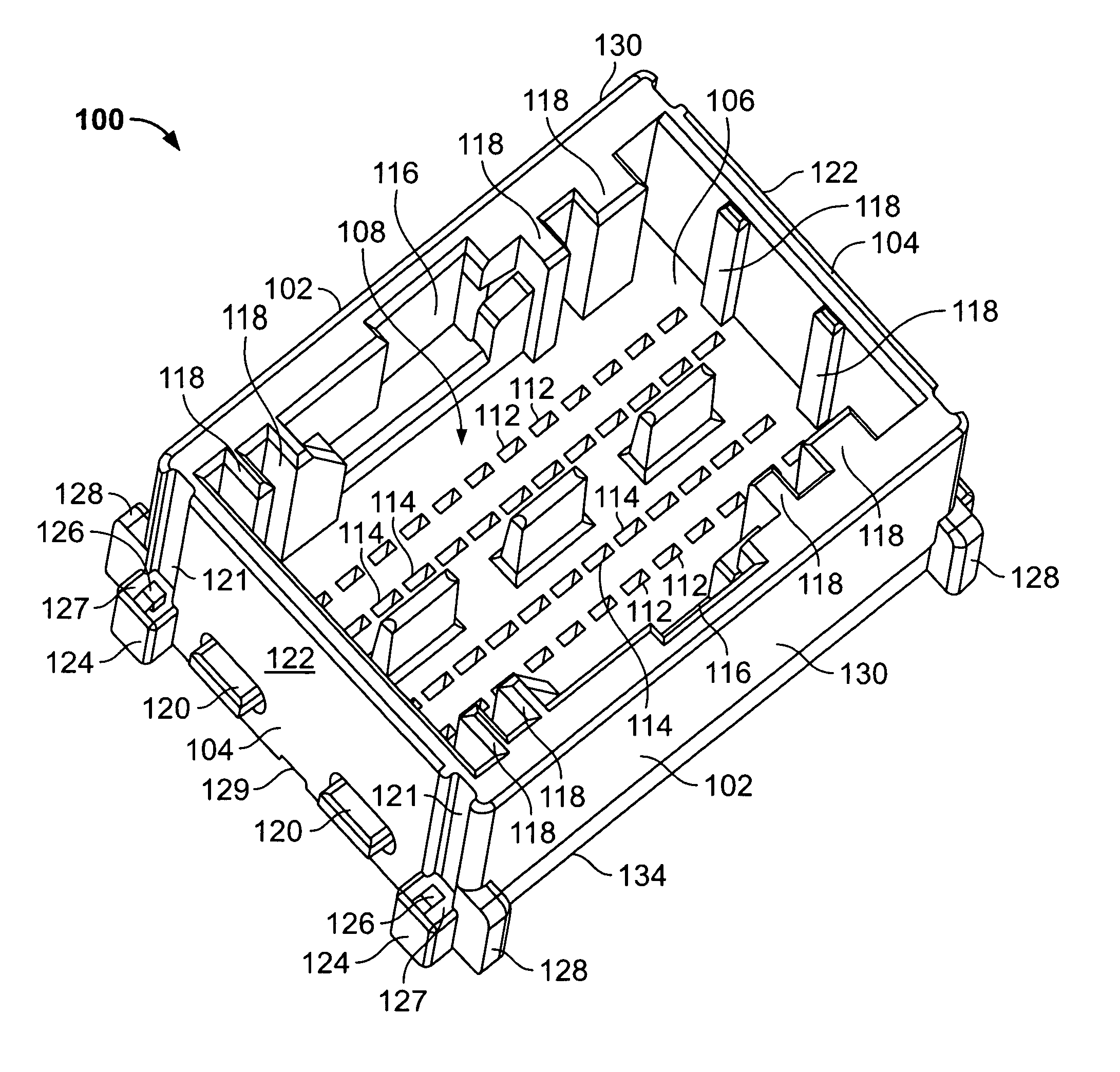
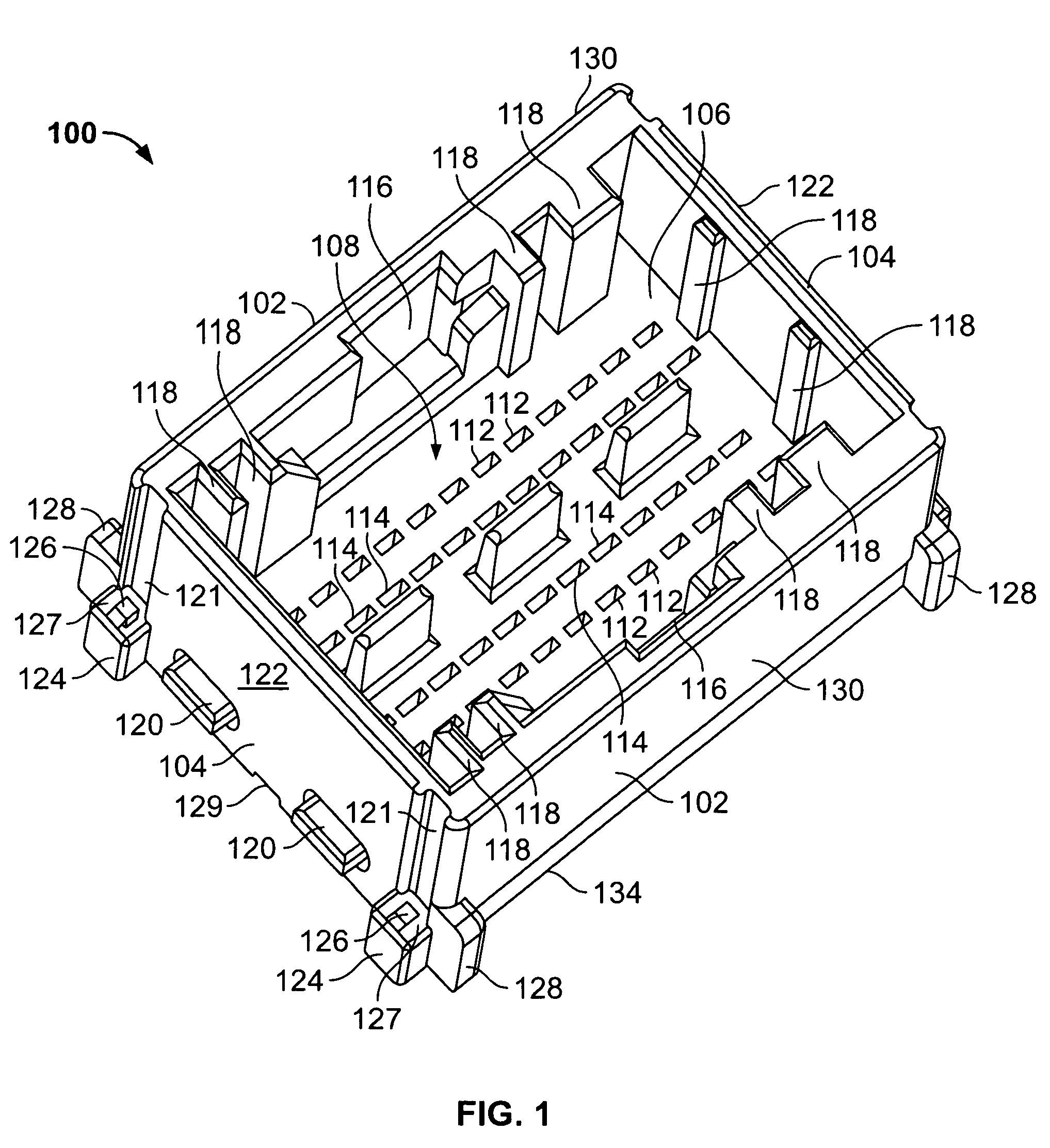
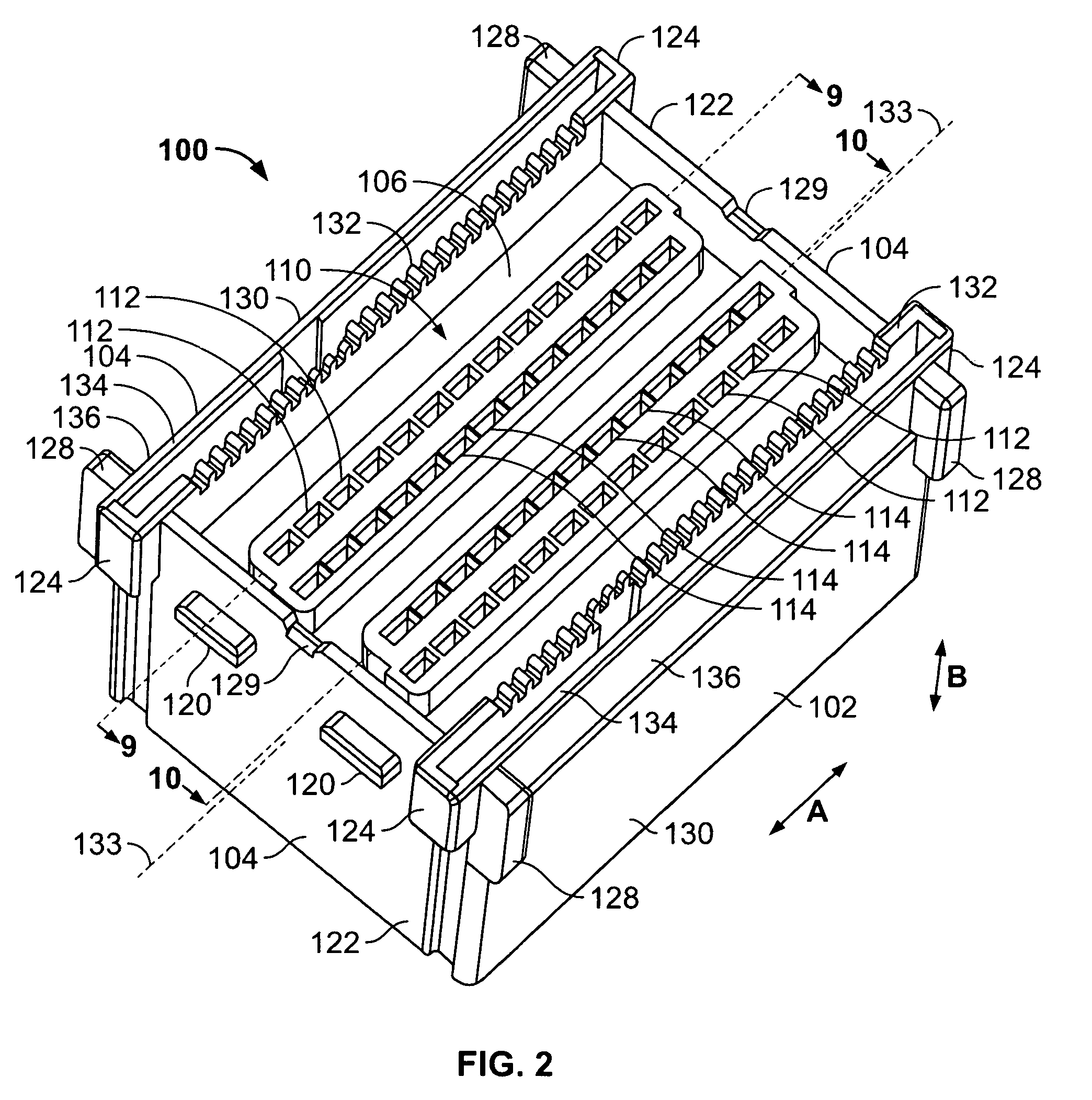
[0033]FIGS. 1 and 2 are top and bottom perspective views, respectively, of a an exemplary housing 100, sometimes referred to as a shroud, for a surface mount header assembly formed in accordance with an exemplary embodiment of the invention.

[0034]The housing 100 includes a pair of longitudinal side walls 102, a pair of lateral side walls 104 extending between the ends of the longitudinal side walls 102, and a bottom wall 106 extending between the longitudinal and lateral side walls 102 and 104. The side walls 102 and 104 and the bottom wall 106 collectively define a contact cavity 108 in the top side of the housing 100 (FIG. 1), and a contact interface 110 on the bottom side of the housing 100 (FIG. 2). A first or outer row of contact apertures 112 and a second or inner row of contact apertures 114 are provided through the bottom wall 106 in a parallel relationship to each of the longitudinal side walls 102 of the housing 100, thereby providing four rows of apertures extending from ...


PUM


Abstract

A header assembly includes an insulative contact housing having a plurality of walls defining an interior cavity and an insulative alignment housing having at least one alignment rib extending on an exterior surface thereof. The alignment housing is separately provided and independently mounted to the contact housing. A plurality of contacts are included within the cavity and extend through one of the walls to an exterior of the contact housing wherein the contacts flex against the alignment housing and abut the alignment rib, thereby ensuring coplanarity of the contacts for surface mounting to a circuit board.

Description

CROSS REFERENCE TO RELATED APPLICATIONS[0001]This application is a continuation-in-part application of U.S. patent application Ser. No. 10 / 718,371 filed Nov. 20, 2003, which is hereby incorporated by reference in its entirety.BACKGROUND OF THE INVENTION[0002]This invention relates generally to electrical connectors, and, more specifically, to surface mount header assemblies for mating engagement with plug assemblies.[0003]The mating of a plug assembly into a receptacle assembly to form a connector assembly often involves a high insertion force. This is particularly true when the connector comprises mating connector housings containing many contacts. For example, automobile wiring systems, such as power train systems, typically include electrical connectors. Typically, each electrical connector includes a plug assembly and a header assembly. The plug assembly is mated into a shroud of the header assembly. The header assembly is in turn mounted on a circuit board along a contact inter...

Claims


Application Information

Patent Timeline
Patent Type & Authority Patents(United States)
IPC IPC(8): H01R12/00H01R4/02H05K1/00H01R12/71H01R43/02
CPCH01R12/714H01R12/724H01R13/506H01R12/712H01R12/716H01R12/57H01R13/24H01R43/0263H01R2201/26H01R12/7029H01R12/7052H01R12/707H01R43/20
Inventor MYER, JOHN MARKMOLL, HURLEY CHESTERFRY, JR., DANIEL WILLIAMS
Owner TYCO ELECTRONICS LOGISTICS AG (CH)
Why Eureka
Try Eureka