
Method for producing a liquid crystal device with low zenithal anchoring energy, and resulting device

Inactive Publication Date: 2006-08-08
NEMOPTIC
View PDF11 Cites 4 Cited by
  • Summary
  • Abstract
  • Description
  • Claims
  • Application Information

AI Technical Summary

Benefits of technology

[0016]It is another object of the present invention to provide a new and improved seat belt electromagnetic lock that may be easily and efficiently manufactured and marketed.
[0017]An even further object of the present invention is to provide a new and improved seat belt electromagnetic lock that has a low cost of manufacture with regard to both materials and labor, and which accordingly is then susceptible of low prices of sale to the consuming public, thereby making such seat belt electromagnetic lock economically available to the buying public.
[0019]Even still another object of the present invention is to provide a seat belt electromagnetic lock for an electrically actuatable locking mechanism for locking a seat belt retractor to prevent withdrawal of seat belt webbing.
[0020]Still yet another object of the present invention is to provide a seat belt electromagnetic lock that eliminates the tension eliminator device to increase seat belt effectiveness.
[0021]Lastly, it is an object of the present invention is to provide a seat belt electromagnetic lock that eliminates the energy absorbing plastic shaft or pendulum actuator of current seat belt designs which only function properly when no slack is present in the seat belt.

Problems solved by technology

Current seat belt designs only work properly if the belt is tensioned around the individual, due to intermittent locking a tension eliminator device was added to seat belts.
If the tension eliminator is misused and a belt is pulled out more than necessary then it becomes ineffective.
Current seat belt designs also do not adequately address the need for side impact protection.
However, the Loomba '603 patent does not include a locking wheel which has cylindrical locking bores, nor does it have cylindrical locking pins which fit within the locking bores, nor does it have a locking key that holds the locking pin within the locking bore, nor does it include a seat belt attached at the bottom central part of the seat, with the belt divided into two parts near the top of the back of the seat with one section extending downward over each side of the front of the seat.
However, the Rumpf et al '317 patent does not include a locking wheel which has cylindrical locking bores, nor does it have cylindrical locking pins which fit within the locking bores, nor does it have a locking key that holds the locking pin within the locking bore, nor does it include a seat belt attached at the bottom central part of the seat, with the belt divided into two parts near the top of the back of the seat with one section extending downward over each side of the front of the seat.
However, the Kato et al '216 patent does not include a locking wheel which has cylindrical locking bores, nor does it have cylindrical locking pins which fit within the locking bores, nor does it have a locking key that holds the locking pin within the locking bore, nor does it include a seat belt attached at the bottom central part of the seat, with the belt divided into two parts near the top of the back of the seat with one section extending downward over each side of the front of the seat.
While the above-described devices fulfill their respective, particular objectives and requirements, the aforementioned patents do not describe a seat belt electromagnetic lock that allows an electrically actuatable locking mechanism for locking a seat belt retractor to prevent withdrawal of seat belt webbing.

Method used


Image

  • Method for producing a liquid crystal device with low zenithal anchoring energy, and resulting device
  • Method for producing a liquid crystal device with low zenithal anchoring energy, and resulting device
  • Method for producing a liquid crystal device with low zenithal anchoring energy, and resulting device

Examples


Embodiment Construction

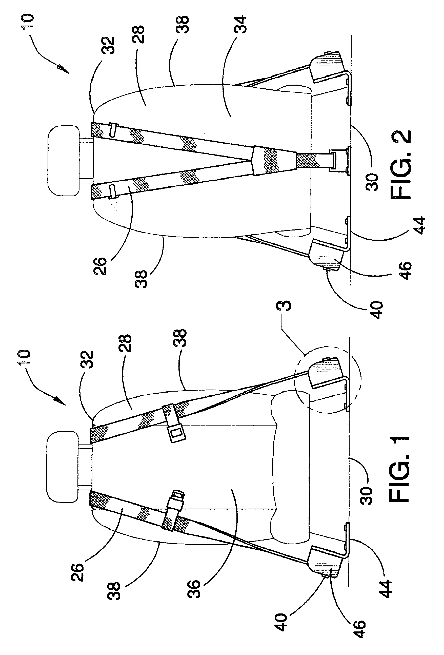
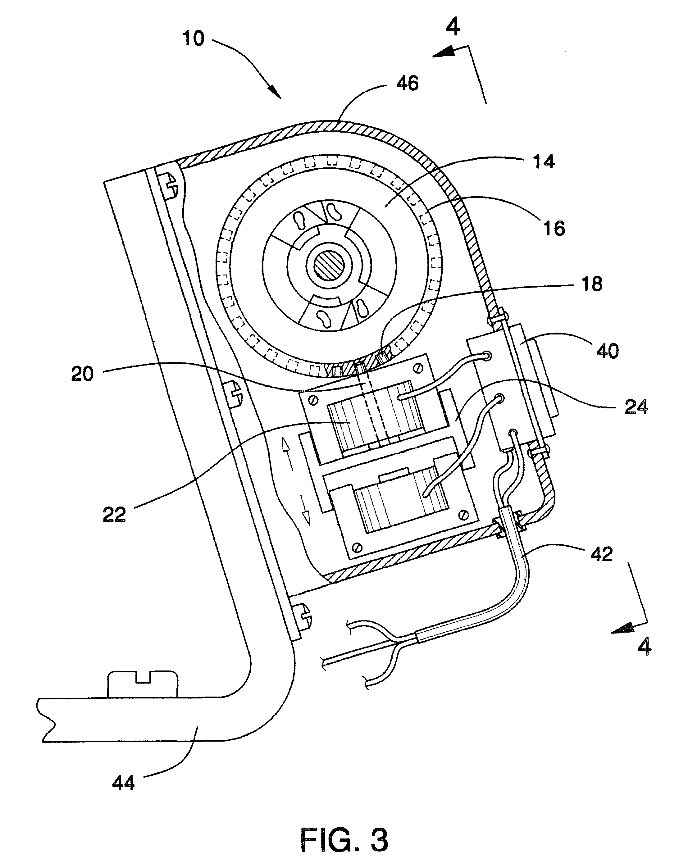
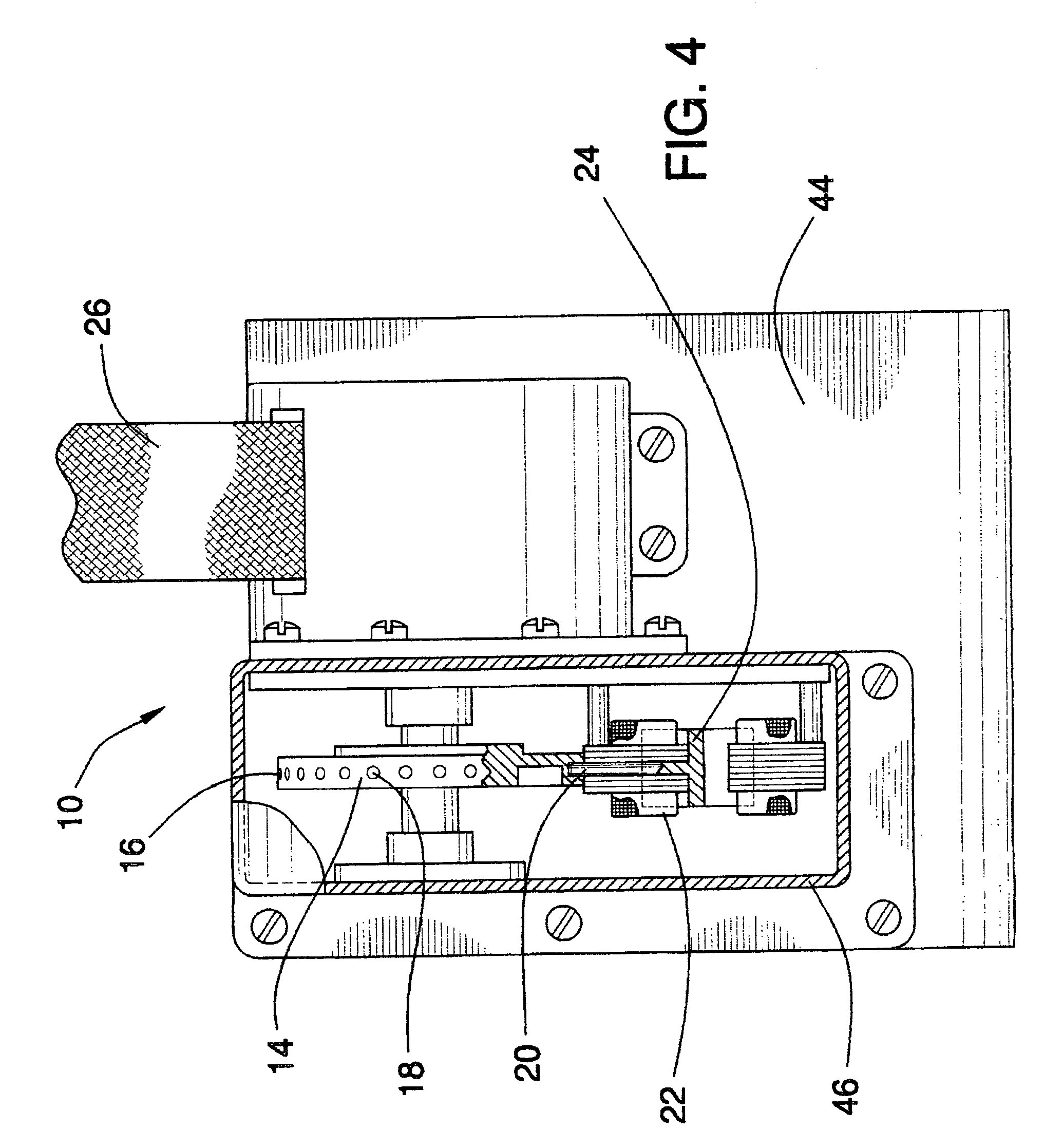
[0030]Referring now to the drawings, and particularly to FIGS. 1–5, a preferred embodiment of the seat belt electromagnetic lock of the present invention is shown and generally designated by the reference numeral 10.

[0031]In FIG. 1, a new and improved seat belt electromagnetic lock 10 of the present invention for the electrically actuatable locking mechanism for locking the seat belt retractor to prevent withdrawal of seat belt webbing is illustrated and will be described. More particularly, the seat belt electromagnetic lock 10 has a seat belt 26. The seat belt 26 sections extending downward over each side 38 of a front 36 of a seat 28. A housing 46 is connected to a mounting base 44. A lock switch 40 is connected to the housing 46.

[0032]In FIG. 2, the seat belt electromagnetic lock 10 of the present invention is illustrated and will be described. The seat belt electromagnetic lock 10 has the seat belt 26. The seat belt 26 is attached at a bottom 30 central part of the seat 28. The...


PUM

PropertyMeasurementUnit
Timeaaaaaaaaaa
Nanoscale particle sizeaaaaaaaaaa

Abstract

A method of making nematic liquid crystal devices where low energy zenith anchoring of the liquid crystal is obtained over confinement plates. A polymer or copolymer is deposited based on PVC onto a substrate. The polymer deposit is stabilized. An azimuth orientation is defined for the deposit to induce controlled azimuth anchoring of the liquid crystal.

Description

BACKGROUND OF THE INVENTION[0001]1. Field of the Invention[0002]The present invention relates to a seat belt electromagnetic lock for use in connection with seat belt retractor. The seat belt electromagnetic lock has particular utility in connection with an electrically actuatable locking mechanism for locking a seat belt retractor to prevent withdrawal of seat belt webbing.[0003]2. Description of the Prior Art[0004]Seat belt electromagnetic locks are desirable for preventing serious injury in the event of a traffic accident. News sources tell us that approximately fifty thousand people are killed in traffic accidents each year, many occur due to side impacts and some occur due to untensioned seat belts. Current seat belt designs only work properly if the belt is tensioned around the individual, due to intermittent locking a tension eliminator device was added to seat belts. If the tension eliminator is misused and a belt is pulled out more than necessary then it becomes ineffective...

Claims


Application Information

Patent Timeline
IPC IPC(8): B05D5/06B05D3/02B05D3/06B05D7/24G02F1/1337G02F1/139
CPCG02F1/133711G02F1/1391Y10T428/1005C09K2323/02G02F1/1337
Inventor LAMARQUE-FORGET, SANDRINEROUX, JULIENDOZOV, IVAN N.MARTINOT-LAGARDE, PHILIPPE R.
Owner NEMOPTIC
Learn More