Wire connecting structure of electromagnetic switch of starter
a technology of electrical switch and connecting structure, which is applied in the direction of engine starters, magnetic bodies, machines/engines, etc., can solve the problems of unstably wired wires in space, difficult to automate the connection of lead wires and conductive terminals, and is likely to brake and interfere with other parts. , to achieve the effect of simplifying the wire connecting structure and improving the resistance to vibration
- Summary
- Abstract
- Description
- Claims
- Application Information
AI Technical Summary
Benefits of technology
Problems solved by technology
Method used
Image

Examples
first embodiment
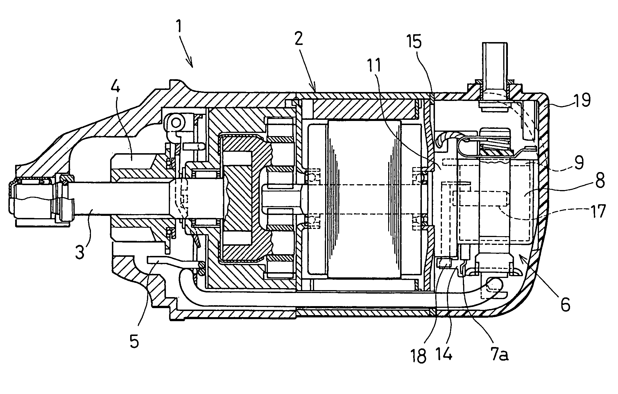
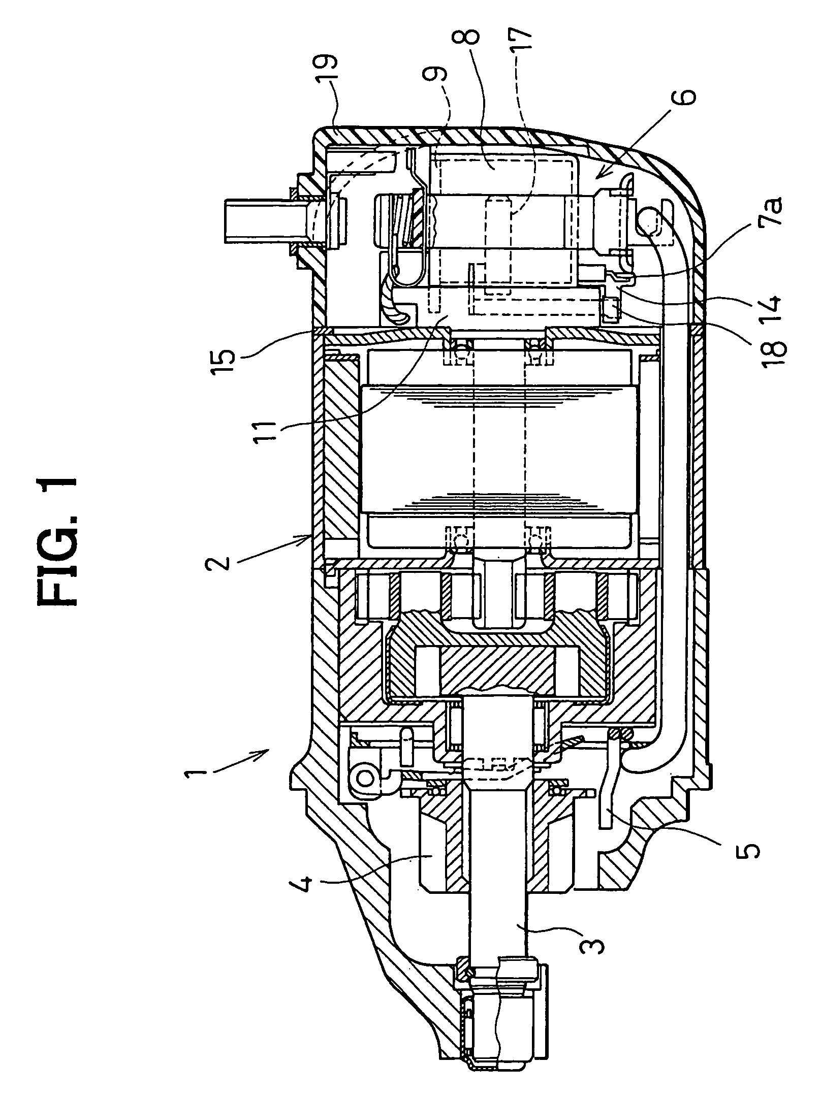
[0026]Referring to FIG. 1, a starter 1 of the embodiment is constructed of a motor 2, an output shaft 3, a pinion 4, a pinion restricting member 5, an electromagnetic switch 6, and the like. The motor 2 generates a rotation force, and the output shaft 3 is driven by the rotation of the motor 2. The pinion 4 is engaged on the output shaft 3 through helical splines. The pinion restricting member 5 restricts rotation of the pinion 4 on starting the motor 2. The electromagnetic switch 6 controls ON / OFF of current supply to the motor 2. For starting an engine, the pinion 4, which is supported in a rotation restricted manner, is moved in axially forward direction (to the left side in FIG. 1) and meshed with a ring gear (not shown) of an engine. The detailed structure and operation of the starter 1 other than the electromagnetic switch 6 are similar to a starter of JP-A-9-79122.
[0027]Hereafter, the detailed structure and the fixing structure of the electromagnetic switch 6 will be describe...
second embodiment
[0049]In the second embodiment, the engaging portion of the male terminal 14 and the female terminal 18 is arranged in a closed space.
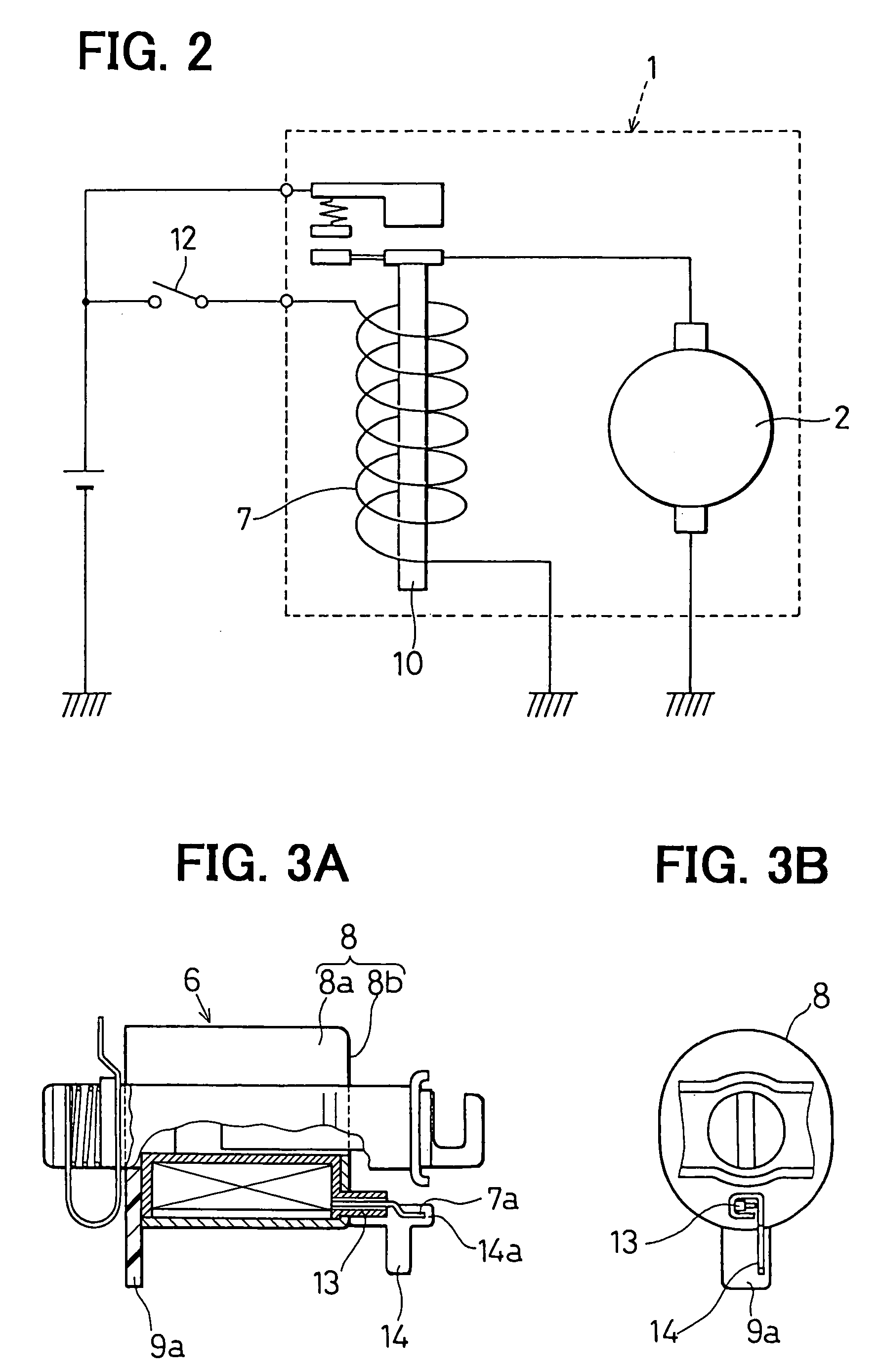
[0050]As shown in FIGS. 5A and 5B, the coil-leading portion 13 is formed to project through the cylindrical wall portion 8a of the switch case 8. The male terminal 14 is fixed to the coil-leading portion 13. Similar to the first embodiment, the lead wire 7a of the exciting coil 7 is led to the outside of the switch case 8 by the coil-leading portion 13 and is connected to the male terminal 14 such as by welding.
[0051]As shown in FIGS. 6 and 7, the female terminal 18 is arranged in a recess portion 11b formed in the seating 11. The recess portion 11b is provided by a recess that is recessed from a supporting surface 11c of the seating 11 and surrounded with walls of the seating 11. The supporting surface 11c supports an outer peripheral surface of the switch case 8.
[0052]In the above configuration, when the electromagnetic switch 6 is mounted on the se...
third embodiment
[0054]In the third embodiment, the male terminal 14 and the 50 terminal 17 are integrated into a single piece, as shown in FIG. 8.
[0055]The male terminal 14 is, as shown in FIG. 8, fixed to the coil-leading portion 13 at a position adjacent to the end frame 19. As the 50 terminal 17, an end of the male terminal 14 passes through the end frame 19 and extends to the outside of the end frame 19.
[0056]In this construction, since the male terminal 14 functions as the 50 terminal 17, the metal member 16 of the first embodiment and the second embodiment is not necessary. As a result, the configuration of the terminal is simplified, and a resistance against the vibration is improved. In the third embodiment, the lead wire 7a is connected to the female terminal 14, which is fixed to the coil-leading portion 13, in a manner similar to that of the first embodiment. Therefore, advantage similar to the first embodiment can be provided.
[0057]The present invention should not be limited to the disc...
PUM
| Property | Measurement | Unit |
|---|---|---|
| fixing strength | aaaaa | aaaaa |
| plate shape | aaaaa | aaaaa |
| conductive | aaaaa | aaaaa |
Abstract
Description
Claims
Application Information
 - R&D
- Intellectual Property
- Life Sciences
- Materials
- Tech Scout
- Unparalleled Data Quality
- Higher Quality Content
- 60% Fewer Hallucinations
Browse by: Latest US Patents, China's latest patents, Technical Efficacy Thesaurus, Application Domain, Technology Topic, Popular Technical Reports.
© 2025 PatSnap. All rights reserved.Legal|Privacy policy|Modern Slavery Act Transparency Statement|Sitemap|About US| Contact US: help@patsnap.com