Electromagnet having spacer for facilitating cooling and associated cooling method

a technology of spacer and electromagnet, which is applied in the field of electromagnets, can solve the problems of not offering the degree of cooling, not often space efficient technique, and heat production, and achieve the effects of improving the efficiency of electromagnet, and imparting different cooling properties to the electromagn

Active Publication Date: 2006-08-08
THE BOEING CO
View PDF15 Cites 44 Cited by
  • Summary
  • Abstract
  • Description
  • Claims
  • Application Information

AI Technical Summary

Benefits of technology

[0014]The present invention therefore provides an improved electromagnet and method for cooling an electromagnet. The spacers offer improved circulation of coolant about the coils by distributing the coolant both circumferentially and longitudinally along the coils of the electromagnet. The spacers include different designs for accommodating different coils and impart different cooling properties to the electromagnet. By including a spacer between each winding layer, each winding of the coil will be adjacent to a spacer such that the coil is uniformly cooled. Providing an efficient cooling spacer will in turn increase the efficiency of the electromagnet by reducing heat, as well as reducing the size of the electromagnet.
[0015]The electromagnet of the present invention is easily manufactured and is capable of being used for a variety of applications. The spacer may be advantageously machined or molded in a planar state and subsequently wrapped about a coil. Thus, different lengths of spacers are easily machined or molded, and the material used for the spacer provides flexibility for wrapping about the coil and maintaining its shape, as well as not damaging the adjacent windings or coils. In addition, the material chosen for the spacer can be easily sized to match the coil dimensions and does not bunch up or require any adjustments.

Problems solved by technology

In either case, as DC or AC is applied to the coil, resistive losses in the coil lead to heat production.
However, this technique is not often space efficient and does not offer the degree of cooling that could be provided by a more effective system of fluid circulation about the coils.

Method used


Image

  • Electromagnet having spacer for facilitating cooling and associated cooling method
  • Electromagnet having spacer for facilitating cooling and associated cooling method
  • Electromagnet having spacer for facilitating cooling and associated cooling method

Examples


Embodiment Construction

[0024]The present invention now will be described more fully hereinafter with reference to the accompanying drawings, in which some, but not all embodiments of the invention are shown. Indeed, this invention may be embodied in many different forms and should not be construed as limited to the embodiments set forth herein; rather, these embodiments are provided so that this disclosure will satisfy applicable legal requirements. Like numbers refer to like elements throughout.

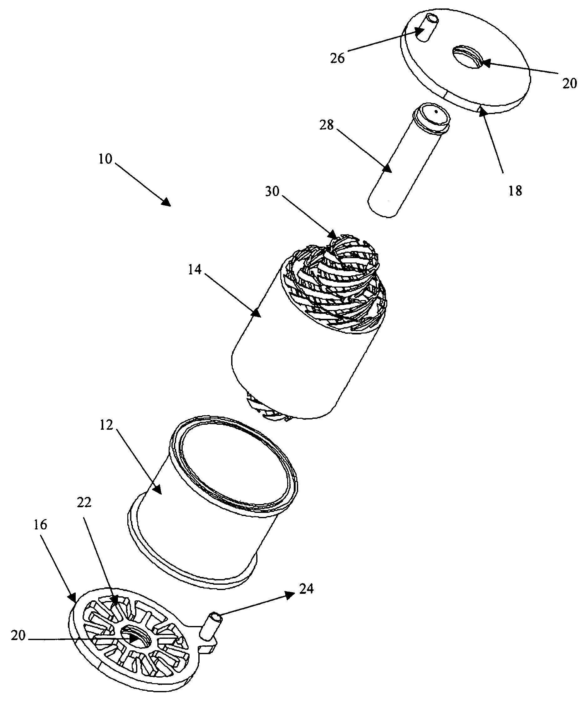
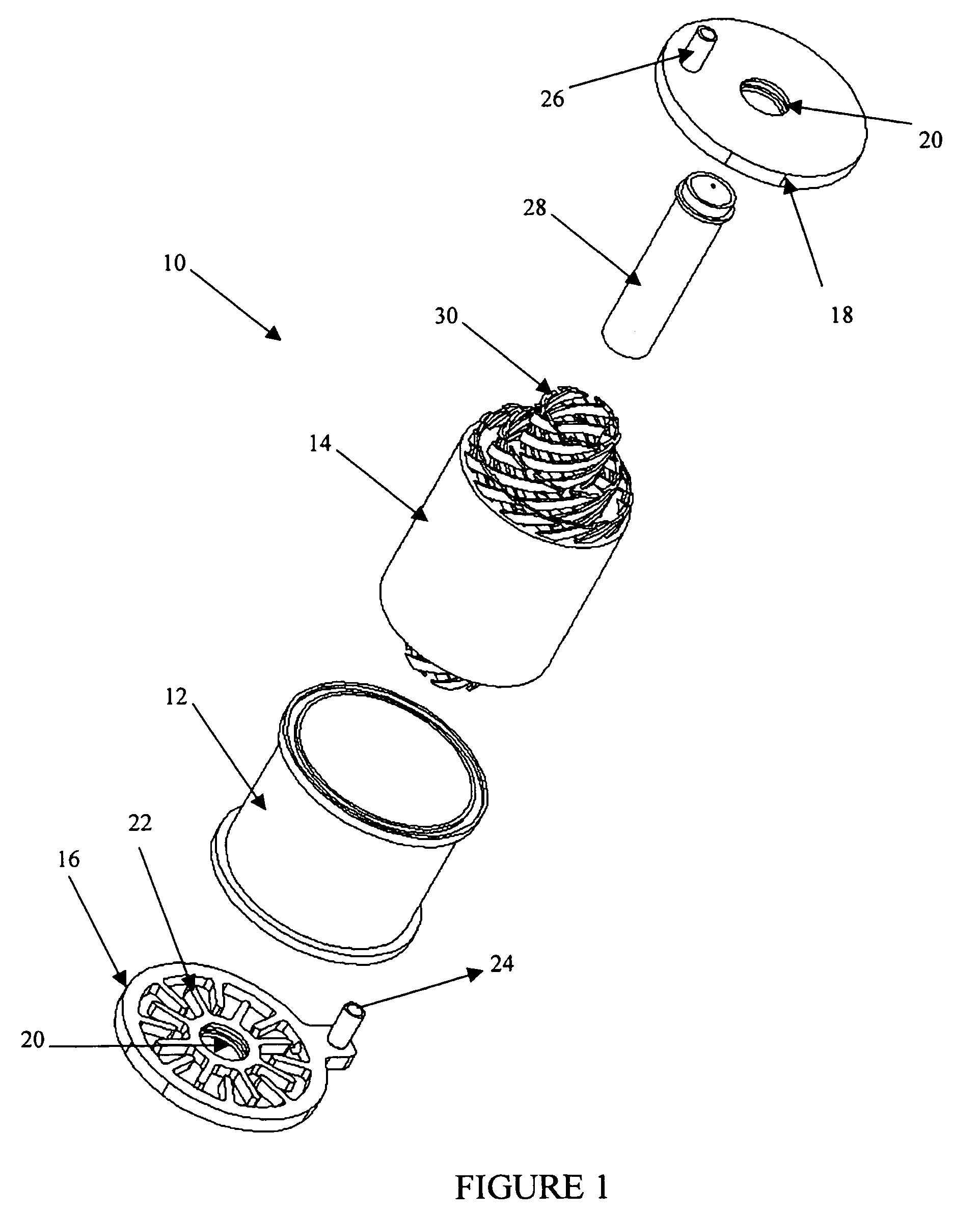
[0025]Referring now to the drawings and, in particular to FIG. 1, there is shown an electromagnet 10. The term “electromagnet” is not meant to be limiting, and it is understood that the term electromagnet could be any device that utilizes current passed through revolutions of conductive wire windings wrapped about a core to create a magnetic field about the core, and causing the core to become magnetized when the core is made of a material of high magnetic permeability. The term electromagnet is also meant to appl...


PUM

PropertyMeasurementUnit
diameteraaaaaaaaaa
widthaaaaaaaaaa
thicknessesaaaaaaaaaa

Abstract

An electromagnet and associated apparatus and method are provided. The electromagnet includes a core and at least one winding disposed circumferentially about the core such that the winding extends at least one revolution around the core. The electromagnet further includes at least one spacer having channels defined therein and disposed circumferentially about the core and adjacent to the at least one winding. The channels facilitate cooling by directing fluid about the windings of the coil as fluid is introduced into the electromagnet.

Description

BACKGROUND OF THE INVENTION[0001]1) Field of the Invention[0002]The present invention relates to electromagnets and, more particularly, to an electromagnet having a spacer that defines channels that facilitate cooling of the electromagnet, as well as an associated apparatus and method.[0003]2) Description of Related Art[0004]Electromagnets are used for various purposes, such as in motors, generators, solenoids, back-up power systems, and transformers. One common application for electromagnets is to provide the actuator mechanism during the installation of rivets or other fasteners, such as in large airframe structures including wing skins, fuselage skins, and the like. Additionally, electromagnets can be used to clamp multiple structures together while drilling or performing a tooling operation on the clamped structures, thereby resulting in a burr-less and debris-free hole. Similarly, an electromagnet may be used to clamp structures together while inserting a rivet or similar faste...

Claims


Application Information

Patent Timeline
Patent Type & Authority Patents(United States)
IPC IPC(8): H01F27/08H01F5/06H01F7/08H01F7/16H01F27/32
CPCH01F5/06H01F7/08H01F7/1607Y10T29/49076Y10T29/49359Y10T29/49075Y10T29/49073H01F27/322
Inventor DAY, ARTHUR C.JOHNSON, PHILIP E.STANLEY, B. DAVID
Owner THE BOEING CO
Why Eureka
Try Eureka