Optical fibre means

a technology of optical fiber and means, applied in the direction of fibre optic/optical waveguide devices, structural/machine measurement, instruments, etc., can solve the problems of secondary damage in the optical system, detection of damage is too late, etc., and achieve the effect of avoiding secondary damag

Inactive Publication Date: 2006-08-08
OPTOSKAND
View PDF10 Cites 41 Cited by
  • Summary
  • Abstract
  • Description
  • Claims
  • Application Information

AI Technical Summary

Benefits of technology

[0007]The object of this invention is to provide a method and a device for detecting a possible damage in an optical fibre at an early stage, in order to avoid any secondary damages in the optical system.

Problems solved by technology

A weakness in all of the detecting systems referred to above is the fact that the detection of a damage comes too late.
When the radiation from the damaged fibre is detected, secondary damages in the optical system might already have occured.

Method used


Image

  • Optical fibre means
  • Optical fibre means

Examples


Embodiment Construction

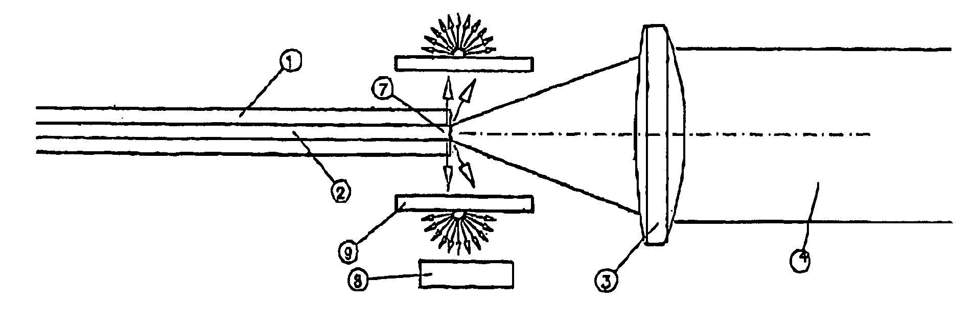
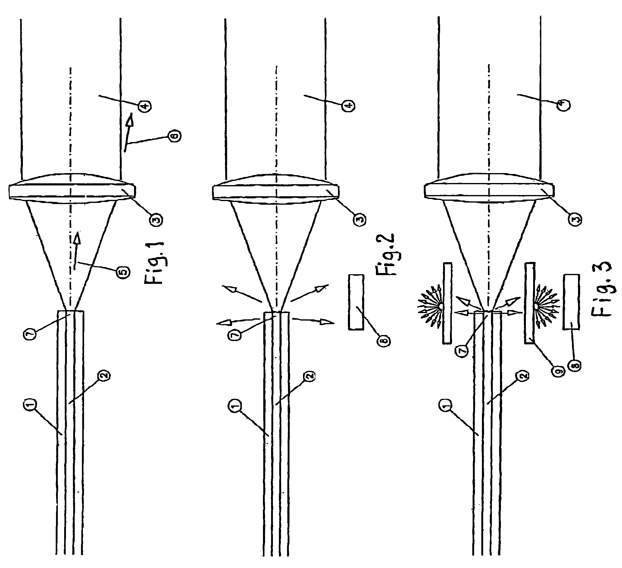
[0016]FIG. 1 illustrates one end 7 of a conventional optical fibre having a core 2, for example of quartz glass, and a surrounding cladding 1 with a lower refractive index than the glass core, for example made of glass or some polymer having a suitable refractive index. The function of the cladding is to keep the radiation in the core so that the radiation is transmitted through the fibre in its longitudinal direction until it leaves the fibre on the exit surface (not shown).

[0017]Outside the cladding 1 of the fibre there are normally further layers arranged in order to, among other things, improve the mechanical strength of the fibre. However, these layers are not illustrated here as they are known per se and not required to explain the idea of the present invention.

[0018]The radiation, for instance in the form of a laser beam 4, is focused on the end surface 7 of the fibre by means of optics in the form of one or more lenses 3 or mirrors. Normally there are some reflection losses ...


PUM

PropertyMeasurementUnit
poweraaaaaaaaaa
average poweraaaaaaaaaa
refractive indexaaaaaaaaaa

Abstract

The present invention relates to a method and a device for detecting damages in an optical fibre (1,2) made for transmitting high optical power, specifically power exceeding 1 kW, and where the optical fibre (1,2) has an entrance end (7) for incident optical radiation (4) and an exit end where the optical radiation is leaving the fibre. According to the invention substantially radially spread radiation in connection with the entrance and / or exit parts of the fibre is detected, and if this radiation exceeds a certain level this is used as an indication of a damage in the entrance and / or exit zone of the fibre.

Description

CROSS-REFERENCE TO RELATED APPLICATIONS[0001]This application claims priority from Swedish patent application 0102718-4 filed 15 Aug. 2001 and is the National Phase under 35 U.S.C. §371 of PCT / SE02 / 01441.FIELD OF THE INVENTION[0002]The present invention relates to a method and a device for detecting damages in an optical fibre made for transmitting high optical power, specifically power exceeding 1 kW, and where the optical fibre has an entrance end for an incident optical beam and an exit end where the optical beam is leaving the fibre.BACKGROUND OF THE INVENTION[0003]Optical fibres for transmitting high optical power are frequently used in industrial applications. Specifically they are used in cutting and welding operations by means of high-power laser radiation, but also in other industrial applications such as heating, detection or working operations in high-temperature environments this type of optical fibres can be used. By means of the optical fibres it is possible to design ...

Claims


Application Information

Patent Timeline
Patent Type & Authority Patents(United States)
IPC IPC(8): G01N21/00G01M11/00G01N21/41G01N21/958
CPCG01M11/35G01N21/88G01N21/958G01N21/412
Inventor BLOMSTER, OLAROOS, SVEN-OLOV
Owner OPTOSKAND
Why Eureka
Try Eureka