Removing residual magnetization in a data transducer

a data transducer and residual magnetization technology, applied in the field of magnetic recording and transmission systems, can solve the problems of affecting the operation of the transducer, affecting the data recording, and undesirably deleting data previously written

Active Publication Date: 2006-08-08
SEAGATE TECH LLC
View PDF28 Cites 21 Cited by
  • Summary
  • Abstract
  • Description
  • Claims
  • Application Information

AI Technical Summary

Problems solved by technology

Such residual magnetism will tend to have a natural decay life and return to the desired net random alignment over time.
However, during this decay interval the aligned magnetism of the pole can adversely affect operation of the transducer by introducing noise in subsequent transmissions.
When the transducer is used to write data to a medium, such magnetization can undesirably erase data previously written to the medium as the medium moves adjacent the transducer.

Method used


Image

  • Removing residual magnetization in a data transducer
  • Removing residual magnetization in a data transducer
  • Removing residual magnetization in a data transducer

Examples


Embodiment Construction

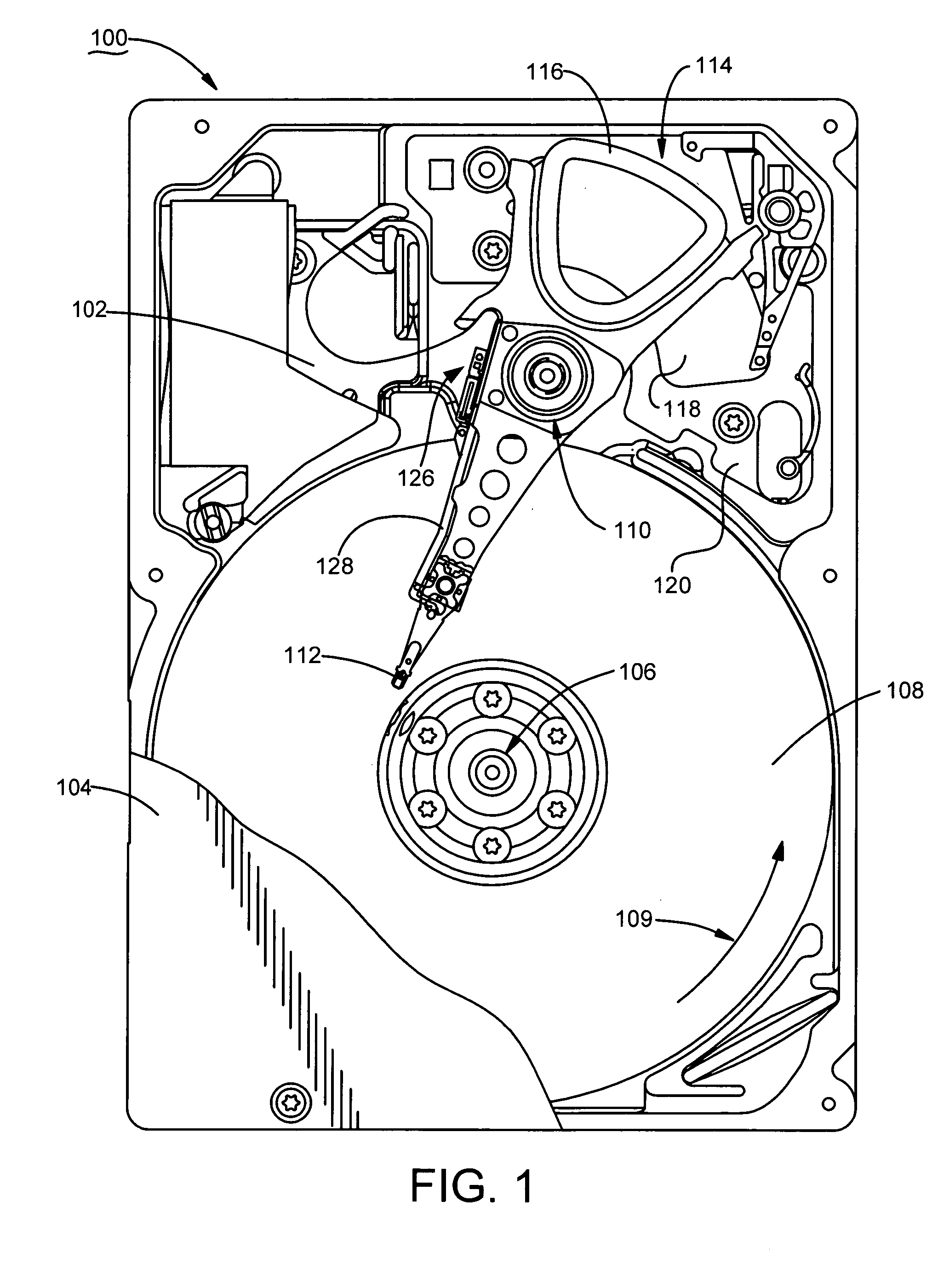
[0022]FIG. 1 provides a top plan representation of a data storage device 100 constructed in accordance with preferred embodiments of the present invention. The data storage device is preferably characterized as a disc drive of the type which magnetically stores and retrieves digital data from and to a host device.

[0023]An enclosed housing 101 defines an internal, environmentally controlled environment for the device 100. The housing 101 is formed by a pair of substantially planar housing members including a base deck 102 and a top cover 104 (shown in partial cut-away in FIG. 1).

[0024]The base deck 102 supports a spindle motor 106 which rotates a plurality of data storage discs (media) 108 at a constant high speed in direction 109. A rotary actuator 110 supports a corresponding number of data transducers 112 (recording heads) adjacent data recording surfaces of the discs 108. The heads 112 are hydrodynamically supported adjacent the disc surfaces via recirculating fluidic currents es...


PUM

PropertyMeasurementUnit
magnetizationaaaaaaaaaa
residual magnetizationaaaaaaaaaa
data transmission currentaaaaaaaaaa

Abstract

Method and apparatus for removing residual magnetization in a data transducer, such as a recording head used to write data to a recording medium in a data storage device. A residual magnetization sense circuit senses a residual magnetization of a pole of the data transducer as a result of the application of a data transmission current to the transducer. A demagnetization current generator removes the residual magnetization by supplying the transducer with a demagnetizing current that decreases to a final magnitude in accordance with a selected profile. The demagnetization current preferably comprises a bi-directional, time varying current of selected frequency to the transducer that tapers linearly, exponentially or in a step-wise fashion to the final magnitude. The demagnetization profile is preferably continuously adapted during operation. Preferably, the sense circuit and demagnetization current generator are incorporated into a preamplifier / driver circuit which performs the demagnetization operation in a self-contained fashion.

Description

FIELD OF THE INVENTION[0001]The claimed invention relates generally to the field of magnetic recording and transmission systems and more particularly, but not by way of limitation, to an apparatus and method for removing residual magnetization in a data transducer.BACKGROUND[0002]Magnetic data transducers are used to transmit data in the form of magnetic pulses. Such transducers (heads) generally comprise a coil that surrounds a magnetically permeable pole structure.[0003]Bi-directional, time varying data transmission currents applied to the coil result in the transmission of corresponding bi-directional, time varying magnetic pulses. In a magnetic transmission system, the pulses are generally conveyed through an appropriate medium to a remote receiver. In a data storage device, such pulses generally operate to magnetically orient a recording medium such as a disc.[0004]It has been observed that at the conclusion of the application of a sequence of data transmission currents, the ma...

Claims


Application Information

Patent Timeline
Patent Type & Authority Patents(United States)
IPC IPC(8): G11B5/03G11B5/02G11B21/02
CPCG11B5/465
Inventor CRONCH, ROBERT D.RAY, JAMES BRIAN
Owner SEAGATE TECH LLC
Why Eureka
Try Eureka