Perpendicular magnetic recording system

a magnetic recording and perpendicular technology, applied in the field of perpendicular magnetic recording system, can solve the problems of increased cost, drop in production efficiency, and increase in consumption of target used in sputtering, and achieve the effect of high recording density

Inactive Publication Date: 2006-08-08
HITACHI GLOBAL STORAGE TECH JAPAN LTD
View PDF14 Cites 2 Cited by
  • Summary
  • Abstract
  • Description
  • Claims
  • Application Information

AI Technical Summary

Benefits of technology

[0011]In view of such problems in the conventional art, it is an object of the present invention to provide a perpendicular magnetic recording system in which a soft magnetic underlayer of a double layered perpendicular magnetic recording medium is prevented from saturation while the soft magnetic underlayer is designed in a thickness smaller than heretofore.

Problems solved by technology

Given here that the growth rates are nearly equal, the growth time becomes more than ten times, causing a drop in production efficiency and a rise in cost.
Moreover, the consumption of the target used in the sputtering also increases for a cost increase.
Besides, greater thicknesses deteriorate surface roughness because of inhomogeneous grain growth.
This causes a problem since high-density magnetic recording media require low surface roughness for the sake of reducing head-medium spacing.
Accordingly, conventional double layered perpendicular magnetic recording media were disadvantageous as compared with in-plane magnetic recording media and single layered perpendicular magnetic recording media.
Nevertheless, when the recording layer of the medium has a relatively high coercivity (Hc), the intensity of write magnetic field must be increased, and the thinning of the main pole produces a problem of main pole saturation.
Furthermore, there are other problems including that no material has been found which can increase the saturation magnetization of soft magnetic underlayers considerably.

Method used


Image

  • Perpendicular magnetic recording system
  • Perpendicular magnetic recording system
  • Perpendicular magnetic recording system

Examples


Embodiment Construction

:

[0037]Hereinafter, description will be given of an embodiment of the present invention.

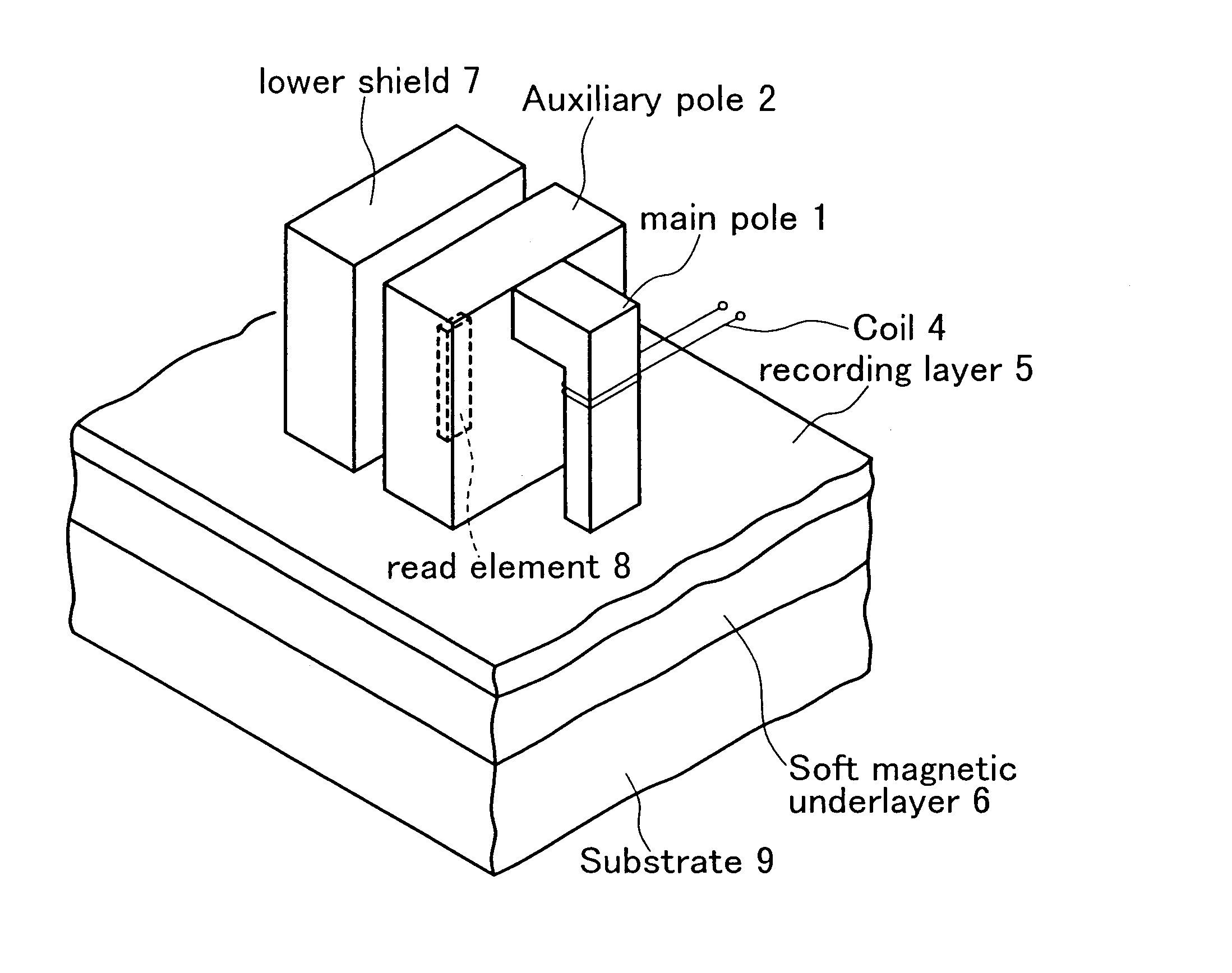
[0038]FIG. 5 is an enlarged view of a magnetic head and magnetic recording medium in a perpendicular magnetic recording system according to the present invention. The magnetic recording medium is a double layered perpendicular magnetic recording medium having a soft magnetic underlayer 6 and a recording layer 5 on its substrate 9. A coil 4 is wound around a main pole 1 of a recording head. A write current flowing through the coil 4 induces write field. The recording head also has an auxiliary pole 2 magnetically coupled to the main pole 1, and is provided with a read element 8 between the auxiliary pole 2 and a lower shield 7 opposed thereto.

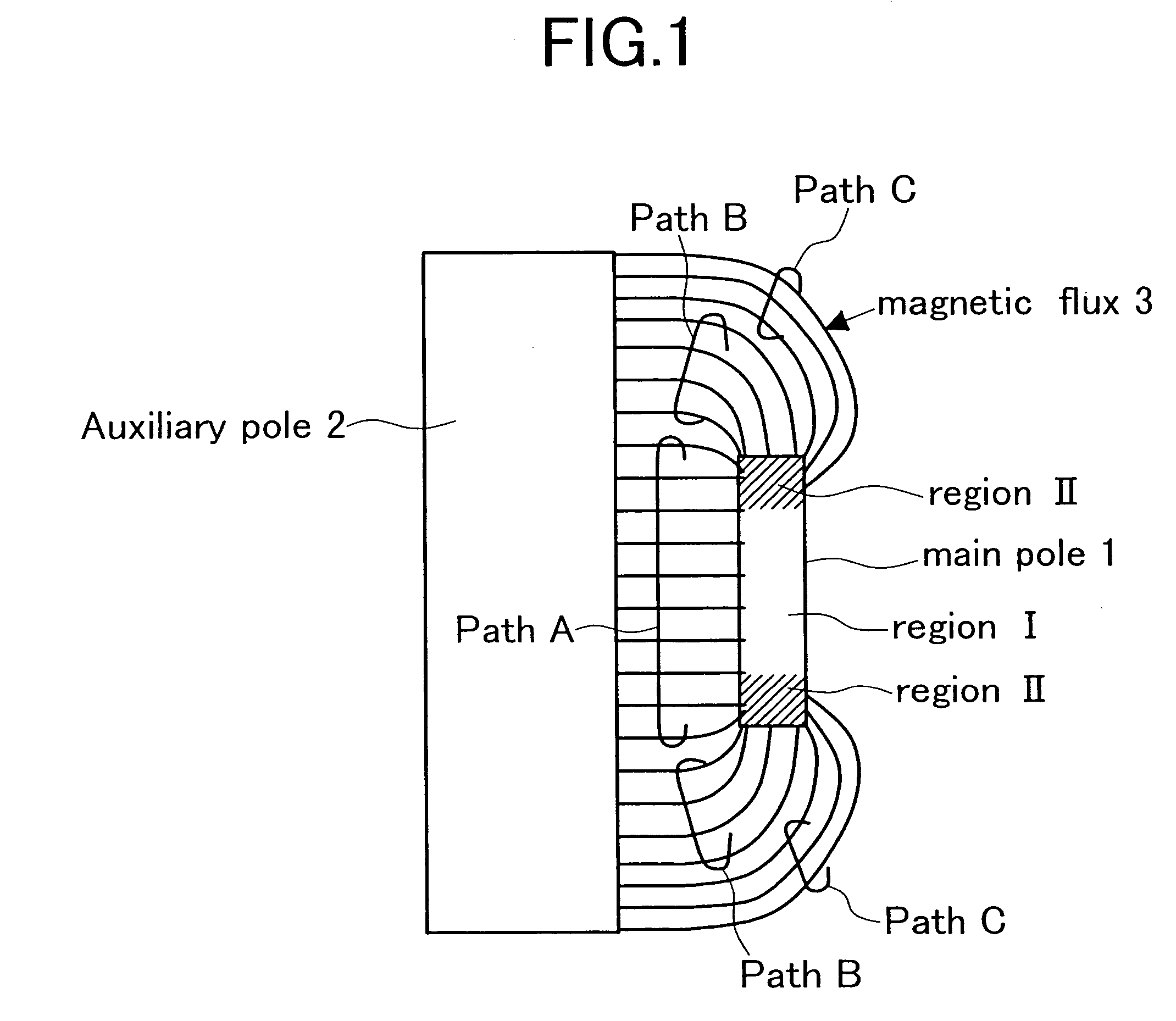
[0039]FIG. 6 is a diagram explaining the magnetic flux in the double layered perpendicular magnetic recording medium and the recording head. As shown in FIG. 6, the magnetic recording medium moves in the direction of the arrow, magnetization transitions being...


PUM

PropertyMeasurementUnit
distanceaaaaaaaaaa
thicknessaaaaaaaaaa
thicknessaaaaaaaaaa

Abstract

To make a soft magnetic underlayer of a double layered perpendicular magnetic recording medium thinner than heretofore while avoiding saturation. Assuming that Tb1 is the thickness of the soft magnetic underlayer of the double layered perpendicular magnetic recording medium, BS2 the saturation flux density of the same, Tm the thickness of a magnetic recording head's main pole 1 along a track direction in the vicinity of its floating surface, TWW the track width of the same, and BS1 the saturation flux density of the same, then Tb1<(BS1×Tm×TWW) / 2(BS2×(Tm+TWW)) is satisfied.

Description

[0001]This is a continuation of application Ser. No. 09 / 785,417 filed Feb. 20, 2001, now U.S. Pat. No. 6,657,813 the content of which is incorporated herein by reference in its entirety.BACKGROUND OF THE INVENTION[0002]1. Field of the Invention[0003]The present invention relates to a perpendicular magnetic recording system using a perpendicular magnetic recording medium (double layered perpendicular magnetic recording medium) having a soft magnetic underlayer.[0004]2. Description of the Related Prior Art[0005]In perpendicular magnetic recording systems using a double layered perpendicular magnetic recording medium, magnetic flux extending from a main pole of a recording head follows a magnetic path that runs through a soft magnetic underlayer of the double layered perpendicular recording medium to enter an auxiliary pole of a magnetic head and then returns to the main pole. Conventional perpendicular magnetic recording media have adopted soft magnetic underlayers of greater design t...

Claims


Application Information

Patent Timeline
Patent Type & Authority Patents(United States)
IPC IPC(8): G11B5/127G11B5/187G11B5/667G11B5/00G11B5/02G11B5/48G11B5/66G11B5/73G11B5/738
CPCG11B5/00G11B5/1278G11B5/73G11B5/667G11B5/488Y10T428/11G11B2005/0029G11B5/7368Y10T428/31826
Inventor NISHIDA, YASUTAKATAKANO, HISASHIMOCHIZUKI, MASAFUMI
Owner HITACHI GLOBAL STORAGE TECH JAPAN LTD
Why Eureka
Try Eureka