

Multilayer capacitor
- Summary
- Abstract
- Description
- Claims
- Application Information
AI Technical Summary
Benefits of technology
Problems solved by technology
Method used
Image

Examples
ninth embodiment
[0243]The configuration of the multilayer capacitor in accordance with a ninth embodiment will be explained with reference to FIG. 13. The multilayer capacitor in accordance with the ninth embodiment differs from the multilayer capacitor C3 in accordance with the eighth embodiment in terms of positions of the first and second inner connecting conductors 130, 140 in the laminating direction. FIG. 13 is an exploded perspective view of the multilayer body included in the multilayer capacitor in accordance with the ninth embodiment.
[0244]As with the multilayer capacitor C3 in accordance with the eighth embodiment, the multilayer capacitor in accordance with the ninth embodiment comprises a multilayer body, first terminal conductors 3A, 3B formed on the multilayer body, second terminal conductors 4A, 4B similarly formed on the multilayer body, first outer connecting conductors 5A, 5B similarly formed on the multilayer body, and second outer connecting conductors 6A, 6B similarly formed o...
tenth embodiment
[0254]The configuration of the multilayer capacitor in accordance with a tenth embodiment will be explained with reference to FIG. 14. The multilayer capacitor in accordance with the tenth embodiment differs from the multilayer capacitor C3 in accordance with the eighth embodiment in terms of the number of inner connecting conductors. FIG. 14 is an exploded perspective view of the multilayer body included in the multilayer capacitor in accordance with the tenth embodiment.
[0255]As with the multilayer capacitor C3 in accordance with the eighth embodiment, the multilayer capacitor in accordance with the tenth embodiment comprises a multilayer body, first terminal conductors 3A, 3B formed on the multilayer body, second terminal conductors 4A, 4B similarly formed on the multilayer body, first outer connecting conductors 5A, 5B similarly formed on the multilayer body, and second outer connecting conductors 6A, 6B similarly formed on the multilayer body, though they are not depicted.
[0256...
eleventh embodiment
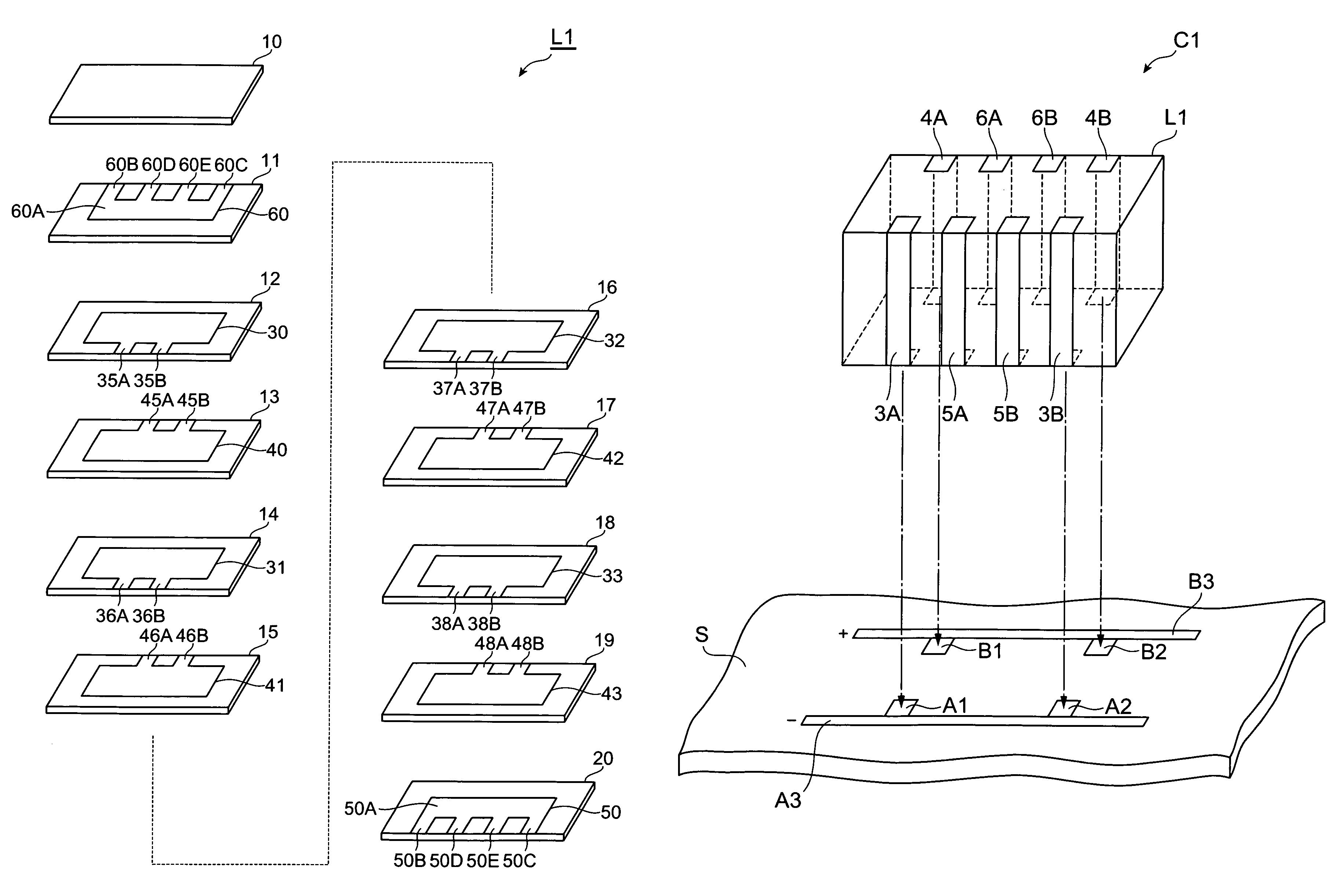
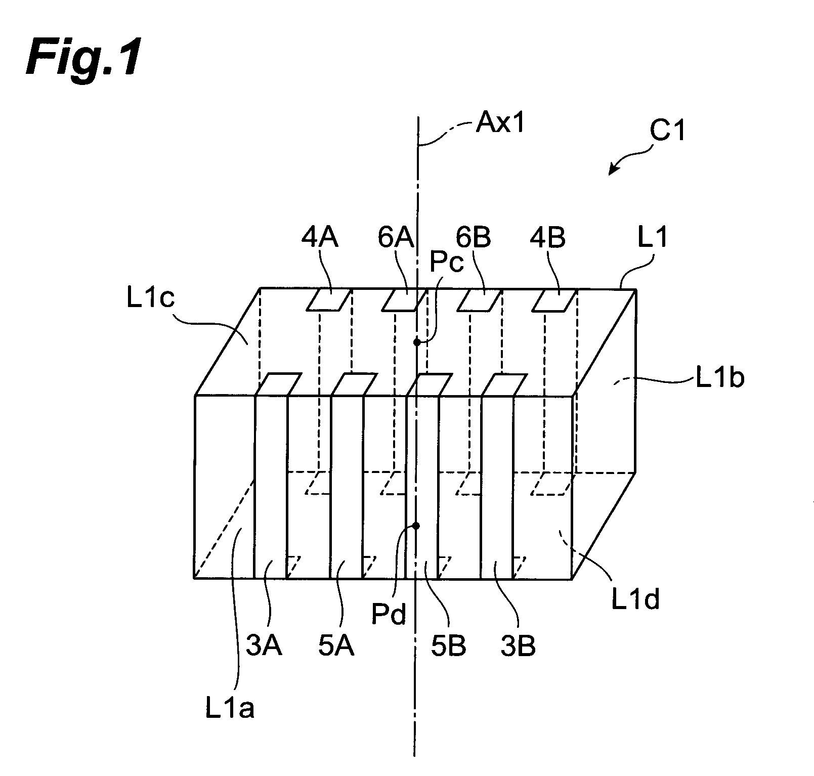
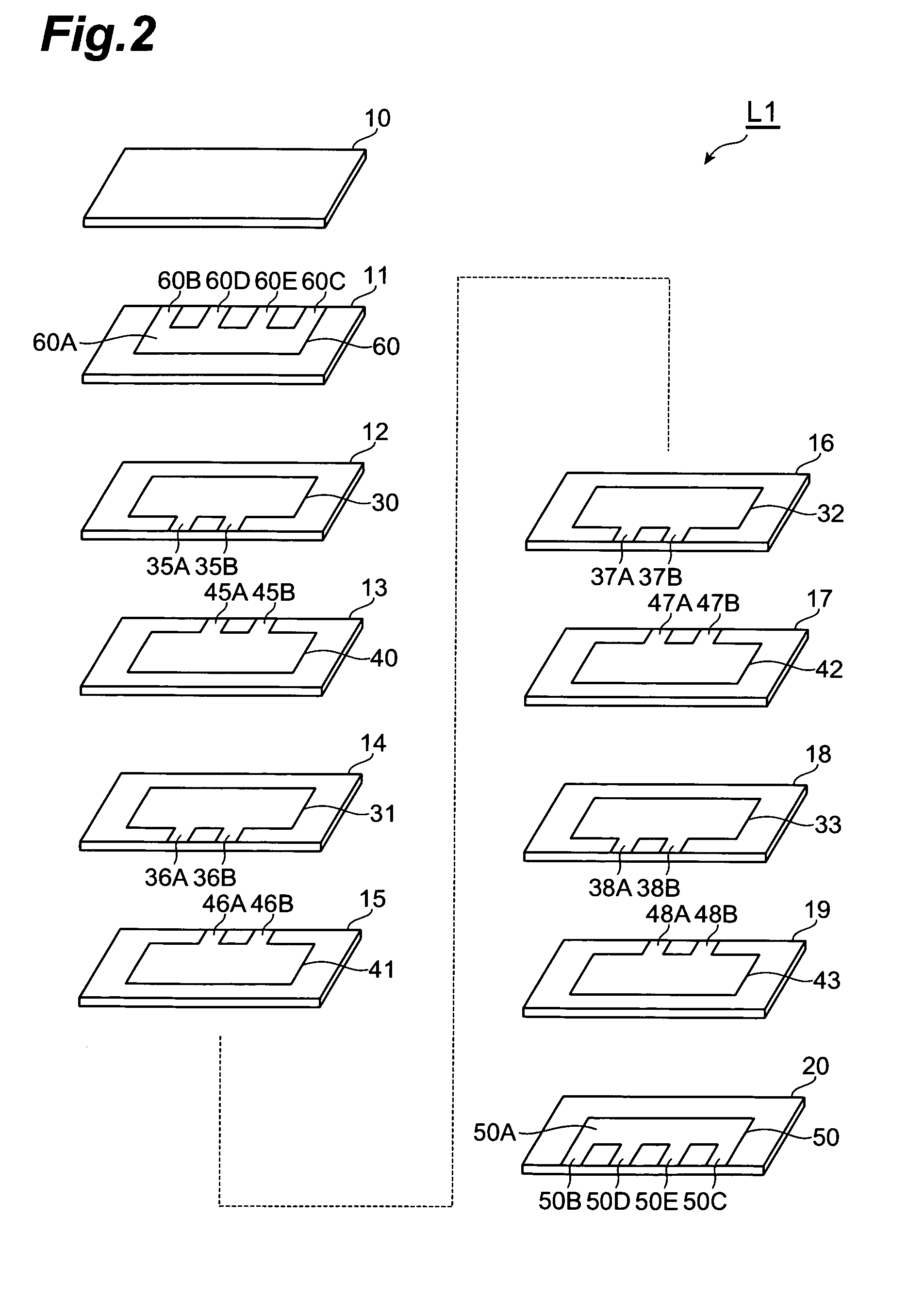
[0267]The configuration of the multilayer capacitor C4 in accordance with an eleventh embodiment will be explained with reference to FIGS. 15 and 16. The multilayer capacitor in accordance with the eleventh embodiment differs from the multilayer capacitor C1 in accordance with the first embodiment in terms of arrangement of outer conductors formed on the first and second side faces of the multilayer body. FIG. 15 is a perspective view of the multilayer capacitor in accordance with the eleventh embodiment. FIG. 16 is an exploded perspective view of the multilayer body included in the multilayer capacitor in accordance with the eleventh embodiment.
[0268]As shown in FIG. 15, the multilayer capacitor C4 in accordance with the eleventh embodiment comprises a multilayer body L4, first terminal conductors 3A, 3B formed on the multilayer body L4, second terminal conductors 4A, 4B similarly formed on the multilayer body, first outer connecting conductors 5A, 5B similarly formed on the multil...
PUM
 Abstract
Description
Claims
Application Information