
Radio method and device having a frame structure

a radio device and frame structure technology, applied in multiplex communication, synchronisation signal speed/phase control, wireless communication, etc., can solve the problems of low number of allowed frequency channels, interference with the operation of rb>, etc., and achieve the effect of reducing overhead and allowing effective utilization of radio resources

Inactive Publication Date: 2006-08-08
ROBERT BOSCH GMBH
View PDF9 Cites 5 Cited by
  • Summary
  • Abstract
  • Description
  • Claims
  • Application Information

AI Technical Summary

Benefits of technology

[0005]The present invention enables voice services to be supported by ATM, e.g., voice-over ATM. The present invention can further allow radio resources to be utilized effectively, since the outlay for overhead decreases due to the relatively large length of a transmission frame. In further refinements of the present invention, collisions can be resolved in a simple manner. The method according to the present invention is very well suited for operating sectorized radio cells.

Problems solved by technology

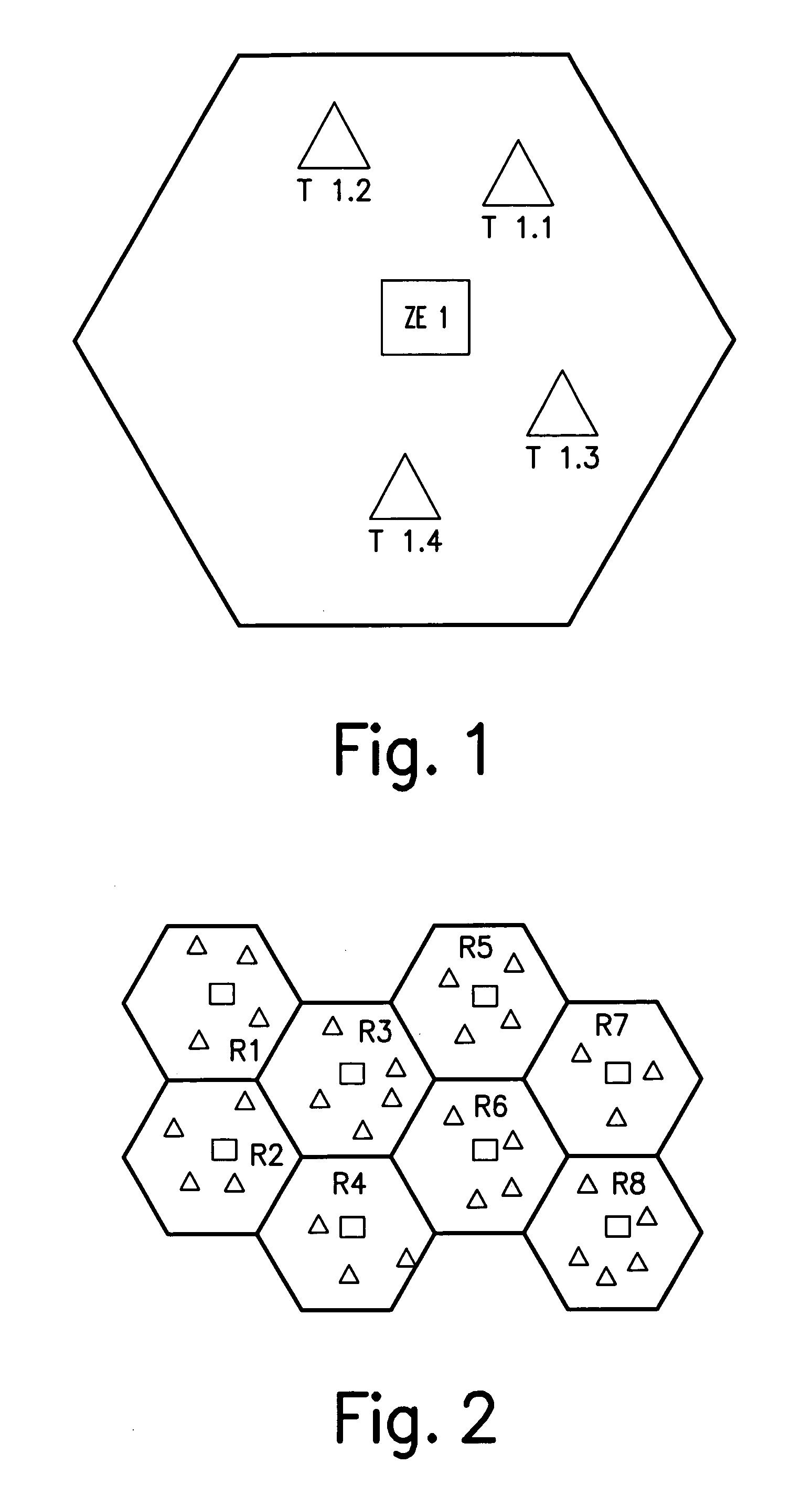
However, if a radio cell is now defined, the terminals and the central unit generate interference which extends beyond the boundary of the radio cell.
Because of the short distance, signals from R4 interfere with the operation of R1, and vice versa.
This problem predominantly occurs when the number of allowed frequency channels is too low.

Method used


Image

  • Radio method and device having a frame structure
  • Radio method and device having a frame structure
  • Radio method and device having a frame structure

Examples


Embodiment Construction

[0016]A protocol (cf. D. Petras, A. Krämling, “MAC protocol with polling and fast collision resolution for an ATM air interface”, IEEE ATM Workshop, San Francisco, Calif., August 1996; D. Petras, A. Krämling, A. Hettich, “MAC protocol for Wireless ATM: contention free versus contention based transmission of reservation requests”, PIMRC' 96, Taipei, Taiwan, October 1996; D. Petras, A. Hettich, A. Krämling: “Design Principles for a MAC Protocol of an ATM Air Interface”, ACTS Mobile Summit 1996, Granada, Spain, November 1996) of layer 2 (DLC layer), can be used for the exemplary embodiment(s) considered here. ATM cells may be used as data packets. However, it is also possible to use data packets of other protocols above the DLC layer, e.g., IP (Internet Protocol), Ethernet, or UMTS. In this case, a layer is introduced between the DLC layer and the protocol of the higher layer, which adapts the data packets of the higher layer to the requirements of the DLC layer.

[0017]In accordance wit...


PUM


Abstract

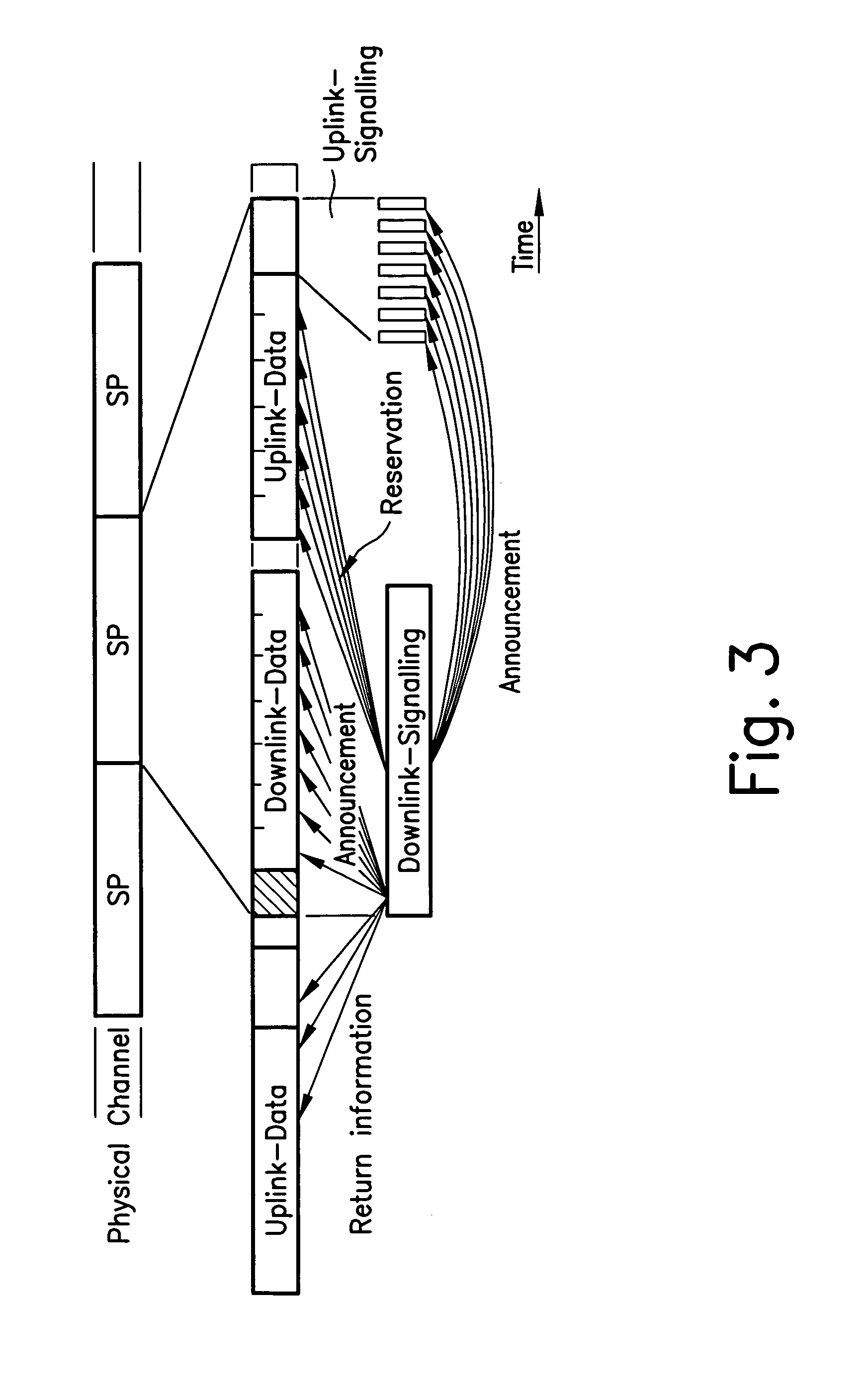
A radio device having a frame structure is proposed for transmitting digital data in a radio communication system, a multiframe being used, which is made of a plurality of containers. The duration of the multiframe can be selected in such a manner that, during this time, a data packet can be filled with voice data of a predetermined bit rate. A container can be selected to be large enough, that a complete transmission frame can be accommodated therein.

Description

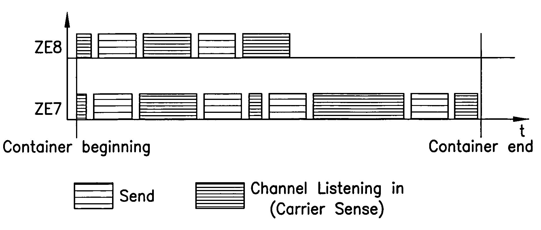
FIELD OF THE INVENTION[0001]The present invention relates to a radio device having a frame structure, for transmitting digital data in a radio communication system.BACKGROUND INFORMATION[0002]Conventional methods in cellular technology allow a frequency band to be used simultaneously by a plurality of radio base stations. In such a radio communication system, several terminals are controlled by a central unit, e.g., a radio base station, which, however, can also be a terminal itself. This central unit defines a radio cell, which indicates the spatial dimensions of the coverage area of the central unit. In general, such radio cells are represented as hexagons or circles in plan view. Such a system is represented in FIG. 1.[0003]FIG. 2 depicts a cellular network having radio cells R1 through R8. However, if a radio cell is now defined, the terminals and the central unit generate interference which extends beyond the boundary of the radio cell. This can completely or partially prevent ...

Claims


Application Information

Patent Timeline
Patent Type & Authority Patents(United States)
IPC IPC(8): H04B7/005H04J3/06H04B7/26H04L7/08H04W16/02H04W68/02
CPCH04B7/2656
Inventor RADIMIRSCH, MARKUS
Owner ROBERT BOSCH GMBH
Learn More