

Method for thermal flow measurement with non constant heating pulses
a technology of thermal flow and heating pulse, which is applied in the direction of volume/mass flow measurement, measurement devices, instruments, etc., can solve the problem of restricting the range of flow rate measurement to the evaluable range, and achieve the effect of short measuring duration, wide range of measurement, and great precision
- Summary
- Abstract
- Description
- Claims
- Application Information
AI Technical Summary
Benefits of technology
Problems solved by technology
Method used
Image

Examples
Embodiment Construction
[0004]The object of the present invention is to provide a method and a device for pulsed mass flow measurement with an improved measuring sensitivity in an enlarged measuring range. This object is achieved according to the invention by the features of the independent claims.
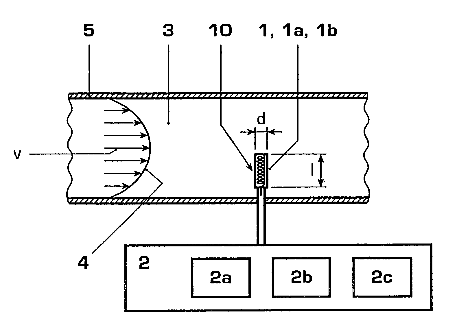
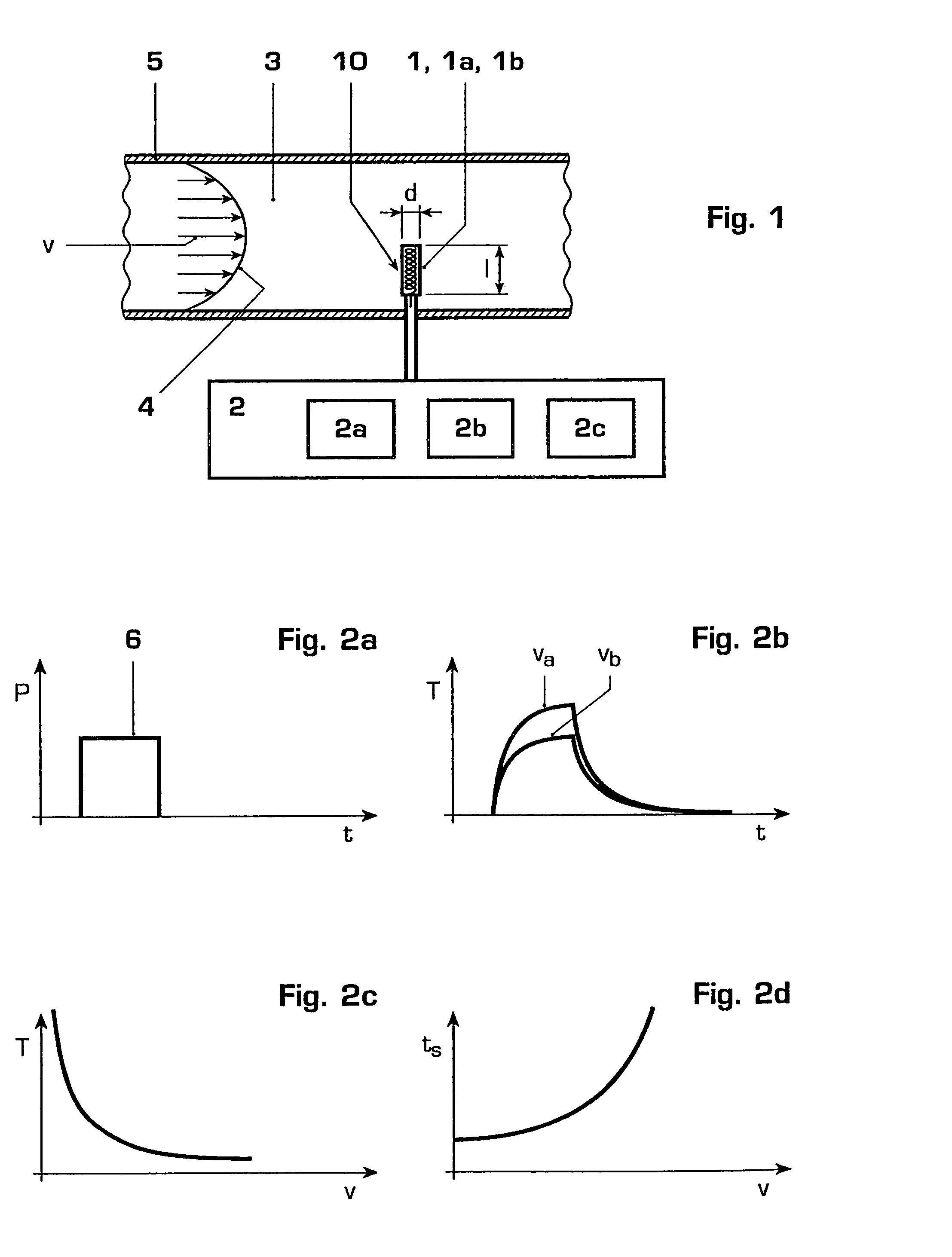
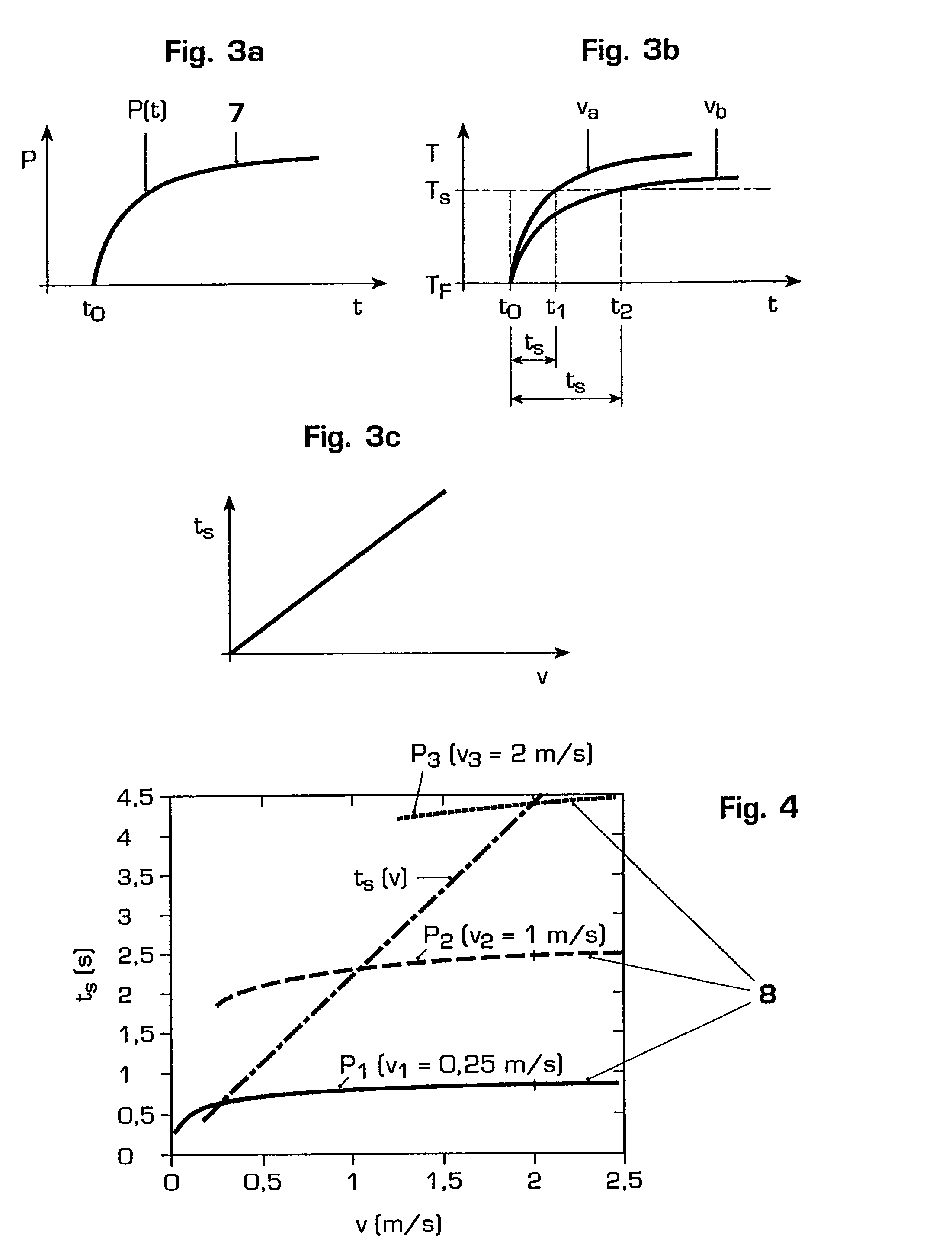
[0005]In a first aspect the invention relates to a method for measuring a flow rate or a mass flow of a fluid, in particular for measuring hot water supply in the private, public or industrial sector, in which the fluid is guided over a sensor element, which has a heating means for inducing temperature changes and a sensor means for determining its temperature, wherein at least from time to time the heating means is operated with a heating power in the form of heating pulses and a flow-dependent threshold value time is measured at the sensor means until a preset temperature threshold value is reached, wherein during at least some of the heating pulses a non-constant heating power with a substantially sublinear bu...
PUM
 Abstract
Description
Claims
Application Information