
Recreational vehicle low temperature water supply warming system

a low-temperature water supply and recreational vehicle technology, applied in positive displacement liquid engines, drawing-off water installations, transportation items, etc., can solve the problems of limiting the use of the great majority of recreational vehicles (rvs) with on-board water systems, consuming the limited on-board fuel supply, and putting a significant load on the on-board battery system. 12v d

Inactive Publication Date: 2006-08-15
KOMRO SR GRANT T
View PDF9 Cites 30 Cited by
  • Summary
  • Abstract
  • Description
  • Claims
  • Application Information

AI Technical Summary

Benefits of technology

[0024]For recreational vehicles 4 equipped with city water inlet line connector 28 and exterior shower 25, these items can be easily protected by simply adding standard water supply tubing, tee connectors 26, two manual 3-way valves 186 and 187 and a drain valve 174 or faucet to isolate and drain these items.
[0033]12) Totally eliminating the need to winterize for many people who live in areas where the temperature never falls below the warming system lower temperature limits, as set by the manufacturer, by simply connecting the unit to an external electrical power outlet.

Problems solved by technology

This common situation greatly limits the use of the great majority of Recreational Vehicles (RVs) with on-board water systems such as motor homes, camper trailers, travel trailers, truck slide-ins and other mobile recreational living structures and units.
Operating these heating devices on 120V AC requires an external power source or running an on-board generator that consumes the limited on-board fuel supply.
Running the heaters on 12V DC puts a significant load on the on-board battery system that is also required to operate essential on-board equipment and devices.
Some larger units employ a multiple battery system that will handle heavier electrical demands but this is costly, requires more space, more weight, more maintenance, and only increases operating time by a relatively small factor.
This type of low temperature protection is generally limited to larger class “A” motor homes that are equipped with high generator capacity and much larger holding tanks than are found in most RV units.
This method reduces valuable interior space.
Another major disadvantage for this method is higher consumption of the limited on-board fuel and electrical supply.
Winterizing the water system when traveling because the outside temperature drops below freezing is troublesome, time consuming and a costly chore.
The few Recreational Vehicle units that offer any real low temperature protection are notably more expensive and really not practical for most Recreational Vehicle owners.
This is a major problem for buyers who must consider the investment verses real use and limited use or opt in favor of other less troublesome and less limiting options.
There seems to be no practical solution or cost effective options available to the vast majority of Recreational Vehicle owners that would allow them to use and enjoy their units to the fullest by extending the recreational season, not by just a few days or weeks but months.
Because the temperatures may drop below freezing for a few hours or even a few days restricts Recreational Vehicle owners to where and when they go.
Although many of these people envy the freedom and mobility offered by smaller recreational trailers, fifth-wheels, slide-ins and smaller motorhomes they are still faced with going south for the better part of the year because of the low temperature limitations.
C) Efficiency and effectiveness of the system is a critical design factor because of limited on-board electrical and fuel supplies.
Because the larger class “A” motor homes are equipped with a larger, high capacity furnace and can have large insulated and heated basement areas for storage, equipment, plumbing lines and holding tanks, the warming system may not be applicable.
Even this limited protection is considered by many RV owners to be a major improvement even though these units would not achieve the full benefit of much lower temperatures the warming system could provide.

Method used


Image

  • Recreational vehicle low temperature water supply warming system
  • Recreational vehicle low temperature water supply warming system
  • Recreational vehicle low temperature water supply warming system

Examples


Embodiment Construction

[0059]While this invention is susceptible of embodiment in many different forms, the figures shown and the specification describes in detail a preferred embodiment of the invention. It should be understood that the drawings and specification are to be considered an exemplification of the principles of the invention. They are not intended to limit the broad aspects of the invention to the embodiment illustrated.

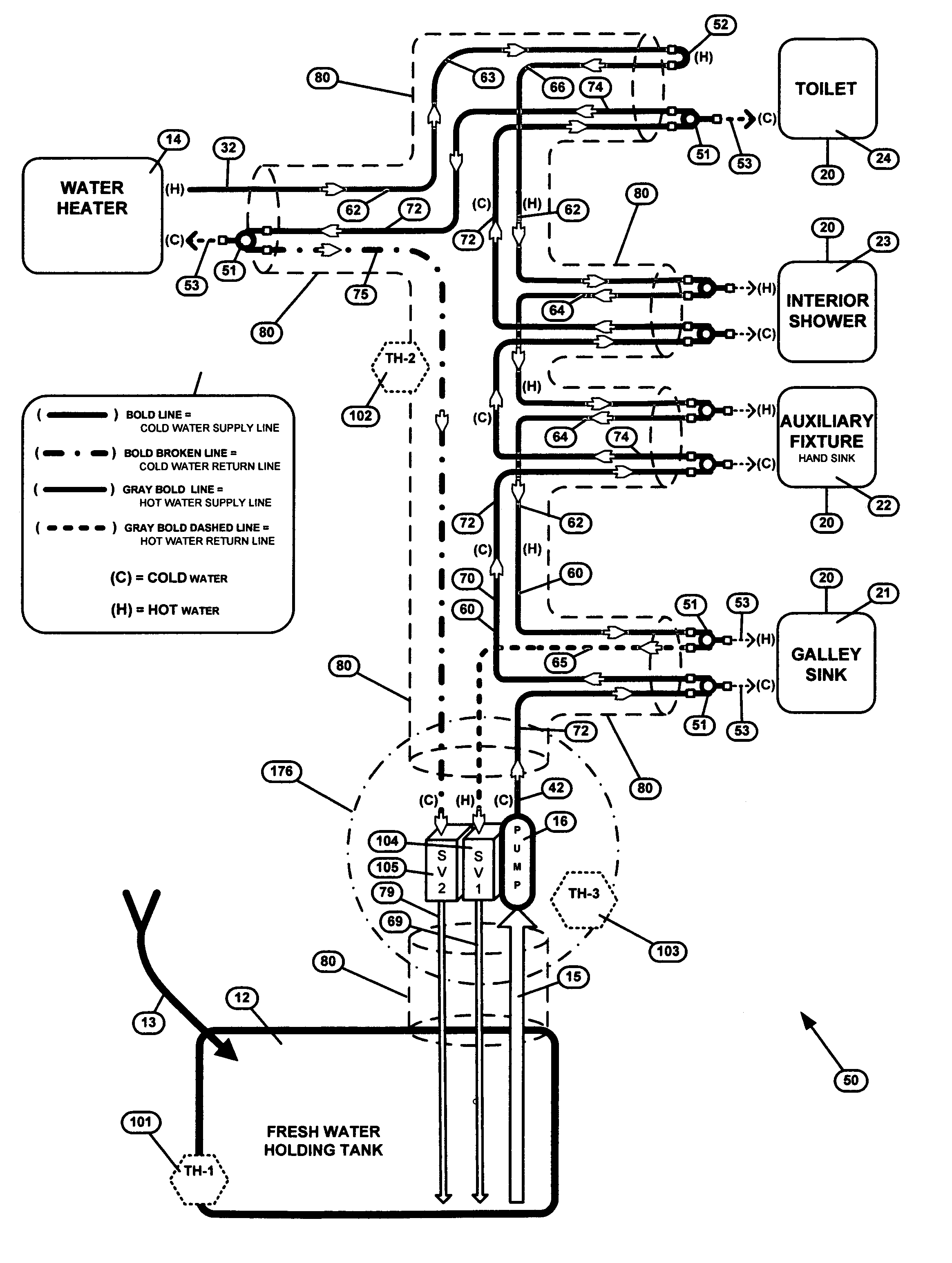
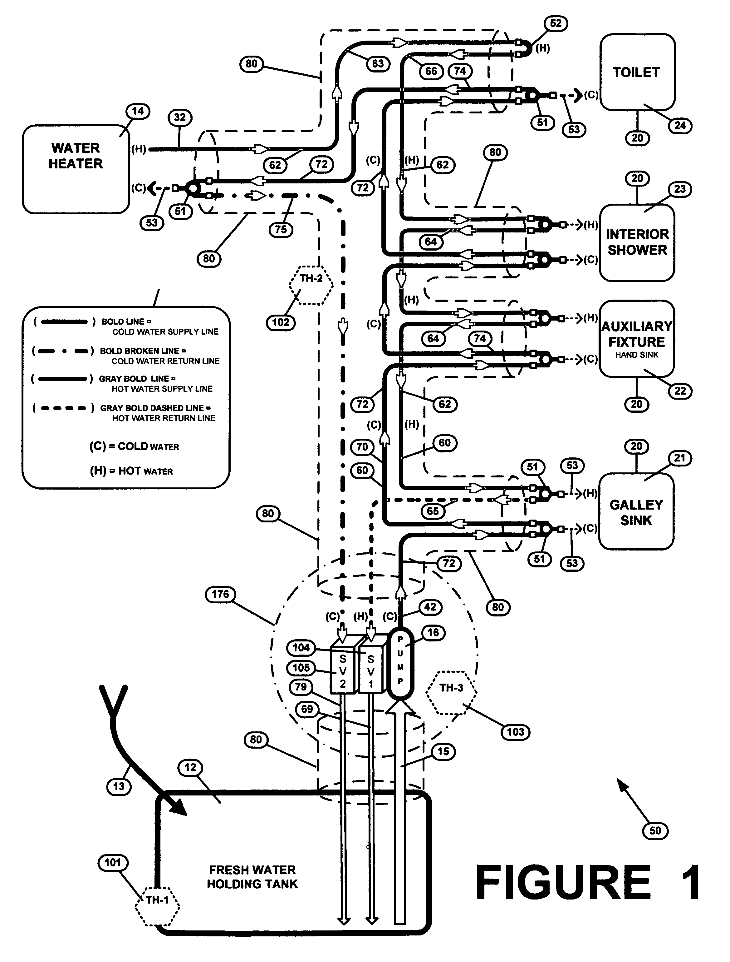
[0060]The present invention relates to an apparatus and method of warming and circulating the water in the fresh water holding tank and the water fixture supply lines of a Recreational Vehicle that is generally indicated by reference numbers 50, 150 or 200 shown in FIGS. 1, 4 and 9, respectively. Each embodiment of the water warming and circulating apparatus and system 50, 150 or 200 includes a holding tank 12, a water heater 14, a pump 16, a water fixture 20, a heated water loop 60 and a cold water loop 70. The location of the hot water heater 14 can differ relative to the pu...


PUM


Abstract

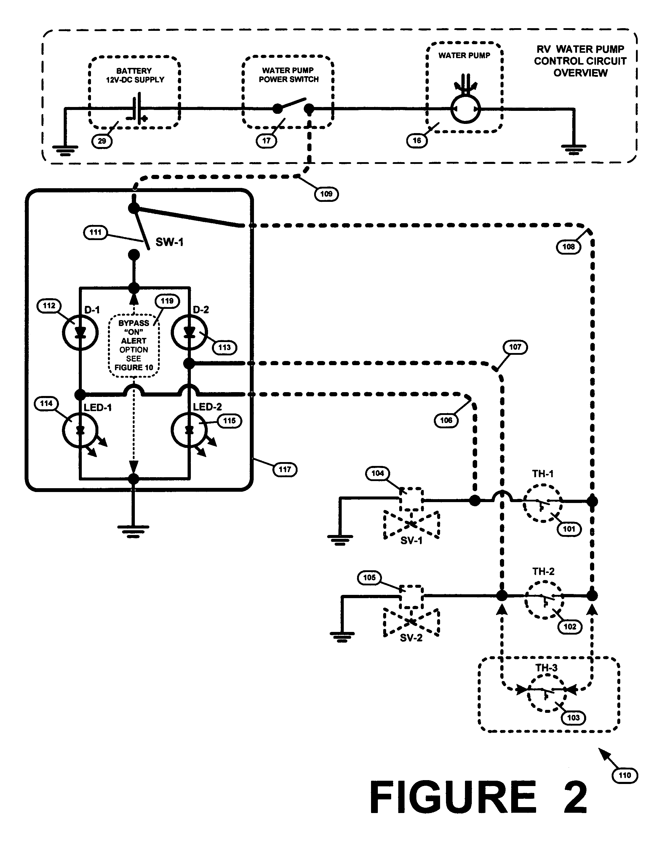
The present recreational vehicle water warming and circulating system uses the heated water in the water heater to heat the on-board water supply when the outside air temperature drops below the freezing point of water. The system includes a holding tank for containing a majority of the on-board water supply, and heated and cold loops that supply heated and cold water to various fixtures in the recreational vehicle. When temperature sensors sense a potentially freezing condition, a control circuit opens one or more solenoid valves to open the one or both loops to return undispensed heated or cold water to the holding tank. The control circuit closes the solenoid valves when the potentially freezing condition is no longer detected by the temperature sensors.

Description

BACKGROUND OF THE INVENTION[0001]For a significant part of the year, large areas in North America have temperatures that fall well below freezing at night (10 or 20 degrees) but are well above freezing during the day. This common situation greatly limits the use of the great majority of Recreational Vehicles (RVs) with on-board water systems such as motor homes, camper trailers, travel trailers, truck slide-ins and other mobile recreational living structures and units. When the outside temperature drops below freezing, the water system must be drained to prevent damage to the pipes, tanks, water fixture(s) and other plumbing components. Very few options are available to avoid this damage. The three basic options are a) drain the water system and go without running water, b) go south to a warmer climate, or c) put the unit in storage.[0002]Some Recreational Vehicles are equipped with dedicated heating devices such as an electric holding tank heaters and pipe heaters. These electric h...

Claims


Application Information

Patent Timeline
Patent Type & Authority Patents(United States)
IPC IPC(8): F16K49/00E03B7/07
CPCE03B7/12B60R15/00Y10T137/5497Y10T137/6416Y10T137/6606Y10T137/6855Y10T137/85954
Inventor KOMRO, SR., GRANT T.
Owner KOMRO SR GRANT T
Learn More