Optimized multiple heat pipe blocks for electronics cooling

a technology of electronics cooling and heat pipe blocks, which is applied in the direction of positive displacement liquid engines, semiconductor/solid-state device details, lighting and heating apparatus, etc., can solve the problems of high-performance electronic devices that often disperse more than 100 w of heat, poor system adaptation to high heat load, and current design limitations

Inactive Publication Date: 2006-08-15
VERTIV CORP
View PDF195 Cites 23 Cited by
  • Summary
  • Abstract
  • Description
  • Claims
  • Application Information

AI Technical Summary

Benefits of technology

[0013]According to another embodiment of the present invention, a method of removing heat from a heat generating device by optimizing boiling of heat pipes in an enclosure is disclosed. The method comprises the steps of: positioning a first heat...

Problems solved by technology

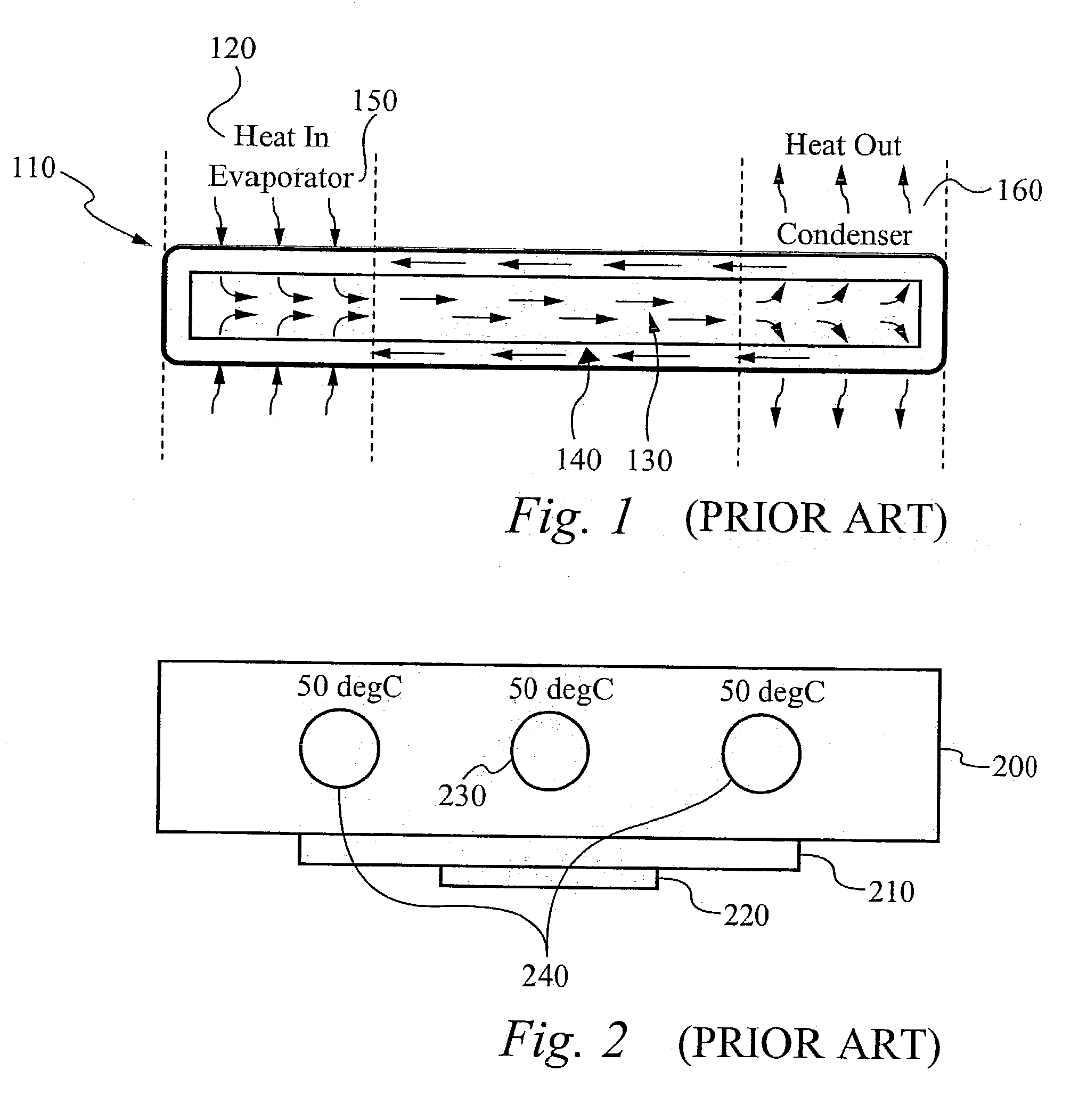
High performance electronic devices often dissipate more than 100 W of heat.
The current designs have an important limitation.
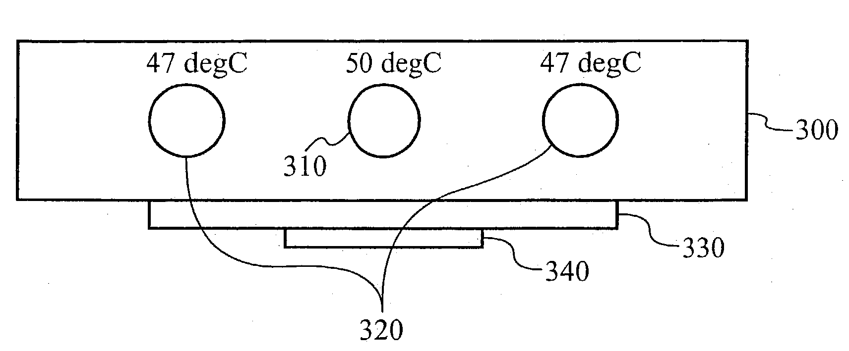
Thus, the center heat pipe 230 will ap...

Method used


Image

  • Optimized multiple heat pipe blocks for electronics cooling
  • Optimized multiple heat pipe blocks for electronics cooling
  • Optimized multiple heat pipe blocks for electronics cooling

Examples


Embodiment Construction

[0022]Reference will now be made in detail to the preferred and alternative embodiments of the invention, examples of which are illustrated in the accompanying drawings. While the invention will be described in conjunction with the preferred embodiments, it will be understood that they are not intended to limit the invention to these embodiments. On the contrary, the invention is intended to cover alternatives, modifications and equivalents, which may be included within the spirit and scope of the invention as defined by the appended claims. Furthermore, in the following detailed description of the present invention, numerous specific details are set forth in order to provide a thorough understanding of the present invention. However, it should be noted that the present invention may be practiced without these specific details. In other instances, well known methods, procedures and components have not been described in detail as not to unnecessarily obscure aspects of the present in...


PUM


Abstract

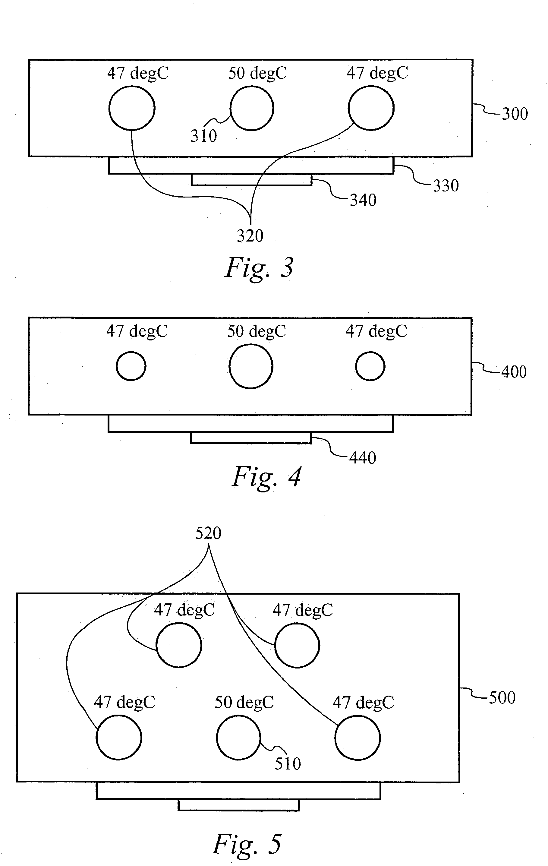
A plate is thermally coupled to a heat generating device and thermally coupled to two heat pipes. Each heat pipe is configured to have a predetermined boiling point temperature selected according to design criteria. One or more additional heat pipes can be coupled to the plate. A heat spreader can be in thermal contact with the heat generating device and with at least one of the heat pipes. The heat pipes can differ in outer cross-sectional dimensions depending on thermal distance position relative to the heat generating device, such that the heat pipes located a farther thermal distance from the heat generating device have smaller outer cross-sectional dimensions than the heat pipes located a shorter thermal distance from the heat generating device.

Description

[0001]This application claims priority under 35 U.S.C. § 119(e) of the co-pending U.S. provisional patent application Ser. No. 60 / 444,269, filed on Jan. 31, 2003, and titled “REMEDIES FOR FREEZING IN CLOSED-LOOP LIQUID COOLING FOR ELECTRONIC DEVICES.” The provisional patent application Ser. No. 60 / 444,269, filed on Jan. 31, 2003, and titled “REMEDIES FOR FREEZING IN CLOSED-LOOP LIQUID COOLING FOR ELECTRONIC DEVICES” is hereby incorporated by reference.FIELD OF THE INVENTION[0002]The present invention generally relates to a method of and apparatus for removing heat from a heat source, in which boiling temperatures of heat pipes are optimized to ensure that the heat pipes start to boil at approximately the same heat load condition from the chip, thereby utilizing the full heat removal capacity of the heat pipes.BACKGROUND OF THE INVENTION[0003]The increasing power of electronic devices is motivating the semiconductor industry to seek effective thermal management solutions. A number of...

Claims


Application Information

Patent Timeline
IPC IPC(8): F28D15/00F28F7/00F04B17/00F28D15/02H01L23/427
CPCF04B17/00F28D15/0266H01L23/427F28D20/026F28F23/00F28F2210/08H01L2924/0002H01L2924/00
Inventor ZHOU, PENGVAN DER HEIDE, DOLFGOODSON, KENNETHUPADHYA, GIRISH
Owner VERTIV CORP
Why Eureka
Try Eureka