Uncooled optical imaging device

Active Publication Date: 2006-08-15
WSOU INVESTMENTS LLC
View PDF8 Cites 3 Cited by
  • Summary
  • Abstract
  • Description
  • Claims
  • Application Information

AI Technical Summary

Problems solved by technology

Referring more particularly to infrared imaging devices, the most serious form of noise is usually the inherent thermal noise of the device, caused by the ambient temperature to which the device is exposed.
The devices used to obtain such cooling are bulky and expensive.
They also introduce serious limitations on the dimensions of the imaging device and / or the cryogenic device and in some cases have a prohibitive power consumption.
The simplest solution, which consists in using cooling by expansion of a gas contained in a pressurized cylinder, although it simplifies the production of the cryogenic device, leads to a considerable consumption of gas and is in practice essentially reserved for single-use devices, such as imaging devices in missiles.
However, this method has the drawback of not providing a reference signal, which degrades the accuracy of the measurements as a function of the temperature of the device.
However, these devices have a temperature drift such that they cannot be used for radiometric measurements.

Method used


Image

  • Uncooled optical imaging device
  • Uncooled optical imaging device

Examples


Embodiment Construction

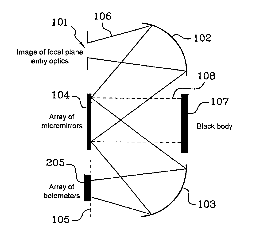
[0021]In FIG. 1, the optical image to the analyzed is formed at the input 101 of an imaging device in accordance with the invention by an external device, not shown, that is known in the art.

[0022]Image transport optics of a type known in the art, in this example comprising two convex mirrors 102 and 103 and an intermediate plane mirror 104, transfer the image to a unit 105 for analyzing the image, for example an array of bolometers.

[0023]According to the invention, the intermediate plane mirror 104 of the transport optics takes the form of an array of micro-electrical-mechanism (MEM) mirrors. The array of micromirrors, which until now has been used mainly in video projectors, comprises a matrix of miniature mirrors whose inclinations can be controlled individually by electrical signals.

[0024]By commanding the inclination of the micromirrors, for example between two distinct states, the image can be formed on the array 105 in a first of these states, as in the case of an ordinary pl...


PUM


Abstract

Optical sensors, more particularly infrared sensors, use an array of MEM micromirrors to chop a light beam impinging on an array of sensors of an imaging device to minimize the influence of thermal noise. The array of micromirrors preferably switches the beam impinging on the array of sensors between an image to be analyzed and an image of a reference black body at a clearly defined temperature. These sensors are not cooled and require no cryogenic devices.

Description

CROSS-REFERENCE TO RELATED APPLICATIONS[0001]This application is based on French Patent Application No. 02 08 895 filed Jul. 15, 2002, the disclosure of which is hereby incorporated by reference thereto in its entirety, and the priority of which is hereby claimed under 35 U.S.C. §119.BACKGROUND OF THE INVENTION[0002]1. Field of the Invention[0003]The present invention relates to optical imaging devices, preferably devices operating in the infrared band, that are not cooled. This kind of imaging device is more particularly intended for use in a video camera or a telescope to form an image outside the visible band. This kind of device is sometimes referred to as an infrared focal plane.[0004]2. Description of the Prior Art[0005]As with any sensor, one of the main qualities required of an optical imaging device is to be able to deliver a signal of sufficient amplitude compared to the inherent noise of the device. Referring more particularly to infrared imaging devices, the most serious...

Claims


Application Information

Patent Timeline
IPC IPC(8): G01J5/02H04N5/225H04N5/33H04N5/361
CPCH04N5/2254H04N5/361H04N5/33H04N23/52H04N25/63
Inventor MAUREL, GILLES
Owner WSOU INVESTMENTS LLC
Why Eureka
Try Eureka