Home-use fuel cell system

Inactive Publication Date: 2006-08-15
HITACHI LTD
View PDF35 Cites 38 Cited by
  • Summary
  • Abstract
  • Description
  • Claims
  • Application Information

AI Technical Summary

Benefits of technology

[0018]Moreover, to achieve the above-described object, according to the present invention, there is provided a home-use fuel cell system for supplying power for power demands of a home, the home-use fuel cell system including a fuel cell for supplying a base power portion except a short-time peak power portion out of the power demands; a power storage device having at least a secondary battery for performing a discharge corresponding to the peak power portion; and a protection mechanism for protecting the secondary battery so that the discharge depth thereof does not exceed a predetermined value.
[0019]The lifet

Problems solved by technology

As a result, the application of fuel cells to small scale power such as power for business-use or home-use has little been taken into consideration.
Such being the case, if the power supply capacity of a fuel call is selected so as to cover power demands at the peak times to apply the fuel cell to home-use power supply, large surplus power will occur in much of the time zone except the

Method used


Image

  • Home-use fuel cell system
  • Home-use fuel cell system
  • Home-use fuel cell system

Examples


Example

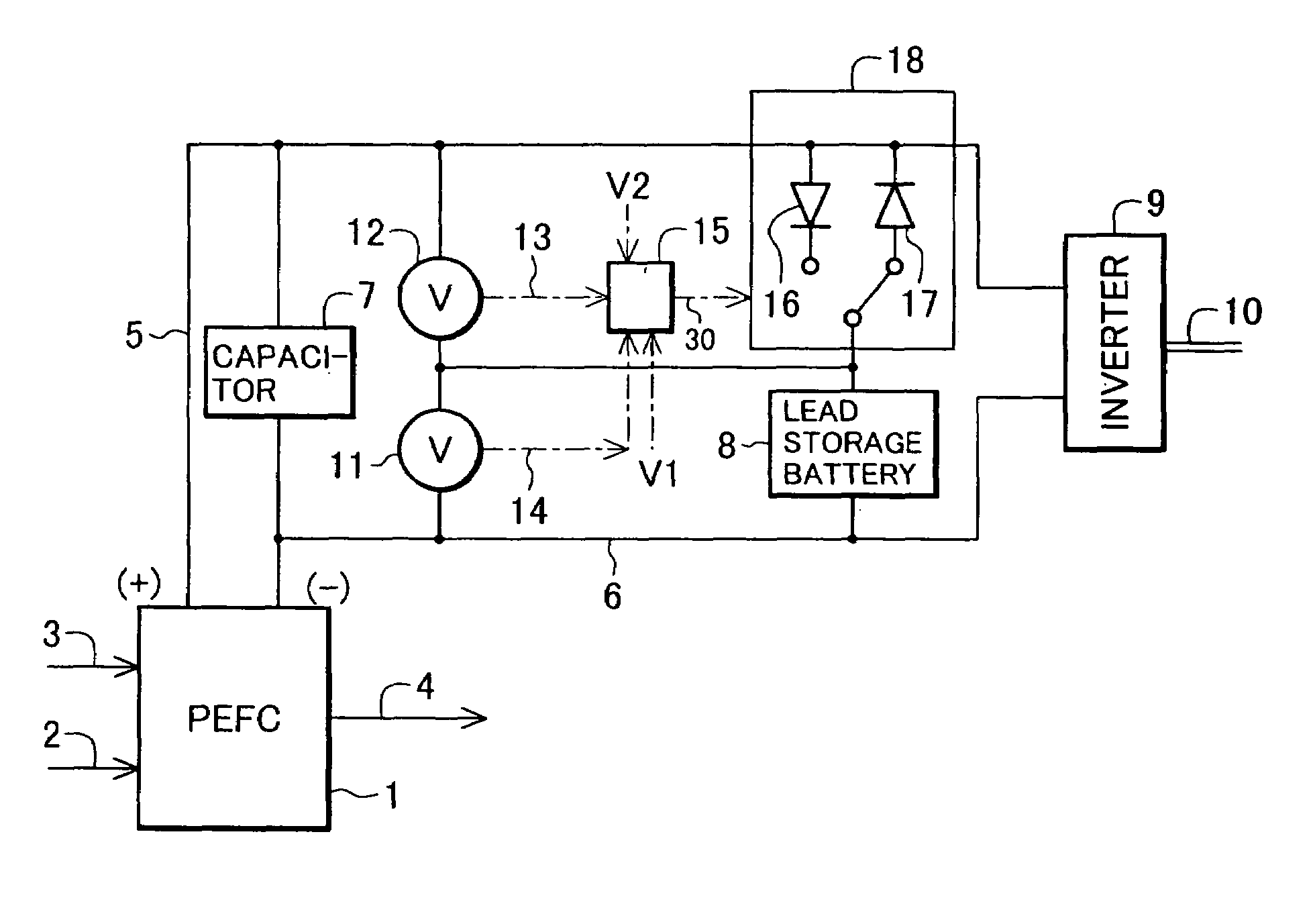
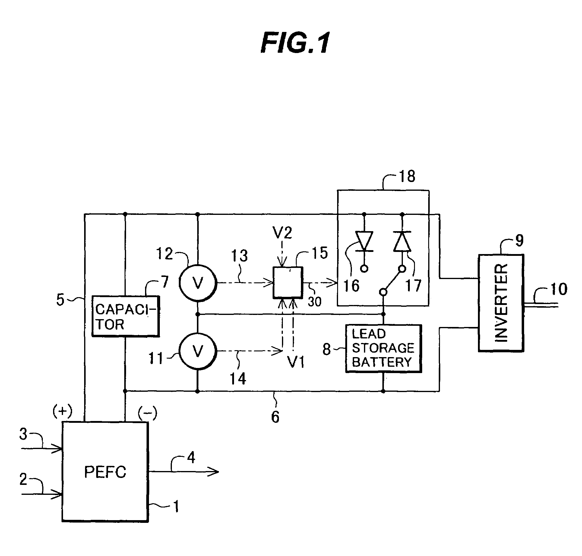
[0031]Hereinafter, an embodiment according to the present invention will be described with reference to the drawings. FIG. 1 is a schematic diagram showing the outline of the construction of an entire home-use fuel cell system (power supply system using a fuel cell) according to this embodiment of the present invention.

[0032]In FIG. 1, the power supply system using a fuel cell comprises a fuel cell that generates direct current power by a reformed fuel containing much hydrogen portion (hereinafter referred to as “hydrogen rich gas”) 3 and air 2, and that is preferably a solid polymer electrolyte fuel cell (hereinafter referred to as a “PEFC” as appropriate) 1; a capacitor that is connected in parallel with a cathode 5 and anode 6 of the PEFC 1, that charges therein a portion of the output of the PEFC 1 when a power demand is smaller than the output of the PEFC 1, that discharges it when the power demand is larger than the output of the PEFC 1, and that is preferably electric double ...


PUM


Abstract

During a time zone where a power demand is smaller than an average value of the entire power demands of homes, an excess portion obtained by subtracting a power demand from a base power portion supplied by PEFC (1) is charged in a capacitor (7) and a lead storage battery (8) in advance; and during a time zone where a power demand is larger than the average value, a peak power portion exceeding this average value is discharged from the capacitor (7) and the lead storage battery (8); thereby enabling the system to sufficiently meet daily home-use demand with requisite minimum equipment while effectively using surplus power. Thus, energy efficiency can be enhanced without wasting energy, and also cost efficiency can be improved.

Description

CROSS-REFERENCE TO RELATED APPLICATION[0001]This is a continuation-in-part of PCT International Application Number PCT / JP01 / 08940 filed on Oct. 11, 2001, the content of which is incorporated herein by reference.BACKGROUND OF THE INVENTION[0002]1. Field of the Invention[0003]The present invention relates to a compact power supply system using a fuel cell as a main power supply, and more specifically, relates to a home-use fuel cell system suitable for a home, which needs relatively large power during a short time period despite its small power demand on average.BACKGROUND ART[0004]2. Description of the Related Art[0005]The fuel cell is a cell that uses, as a core matter, a combustible chemical matter such as hydrogen, carbon monoxide, hydrocarbons or the like, or a fuel comprising some of them, and that allows the chemical matter or fuel to electrochemically perform oxidation reaction, thereby directly converting the energy change in an oxidation process into electrical energy. The f...

Claims


Application Information

Patent Timeline
IPC IPC(8): H02P9/04F03D7/00H02J7/00H02P9/00H01M16/00H02J3/32H02J7/34
CPCH01M16/006H02J3/32H02J7/345H02J7/34Y02B10/30H02J2001/004H02J2300/30Y02E60/50Y02E60/10
Inventor OKUSAWA, TSUTOMUYOKOMIZO, OSAMUKAHARA, TOSHIKICHINO, KOUICHIMIZUKAMI, TAKAAKITAKAHASHI, SHIN
Owner HITACHI LTD
Why Eureka
Try Eureka