Fixing member

a fixing member and member technology, applied in the field of inductance, can solve the problems of inapplicability of methods and cable damag

Inactive Publication Date: 2006-08-15
ABB (SCHWEIZ) AG
View PDF7 Cites 2 Cited by
  • Summary
  • Abstract
  • Description
  • Claims
  • Application Information

AI Technical Summary

Benefits of technology

[0008]The fixing member according to the invention is characterized in that it has the shape of a thin-walled cylinder with an inner and an outer envelope surface, the inner envelope surface surrounding the outside of the cable winding. Because the fixing member surrounds and clamps the cable winding, the cable is fixed in the winding and is thus prevented from being mechanically damaged by the short-circuit forces to which the cable is subjected during a short-circuit. The short-circuit forces acting in the radial and axial directions are absorbed by the friction between the cable and the fixing member and by the stiffness in the fixing member.

Problems solved by technology

When the inductor is short-circuited, both these types of mechanical stresses may lead to the cable being damaged.
However, WO 98 / 34243 is limited to primarily absorbing short-circuit forces acting in the axial direction since no prestress in the radial direction occurs.
However, for reactors with one winding only, this method is not applicable.

Method used


Image

  • Fixing member
  • Fixing member
  • Fixing member

Examples


Embodiment Construction

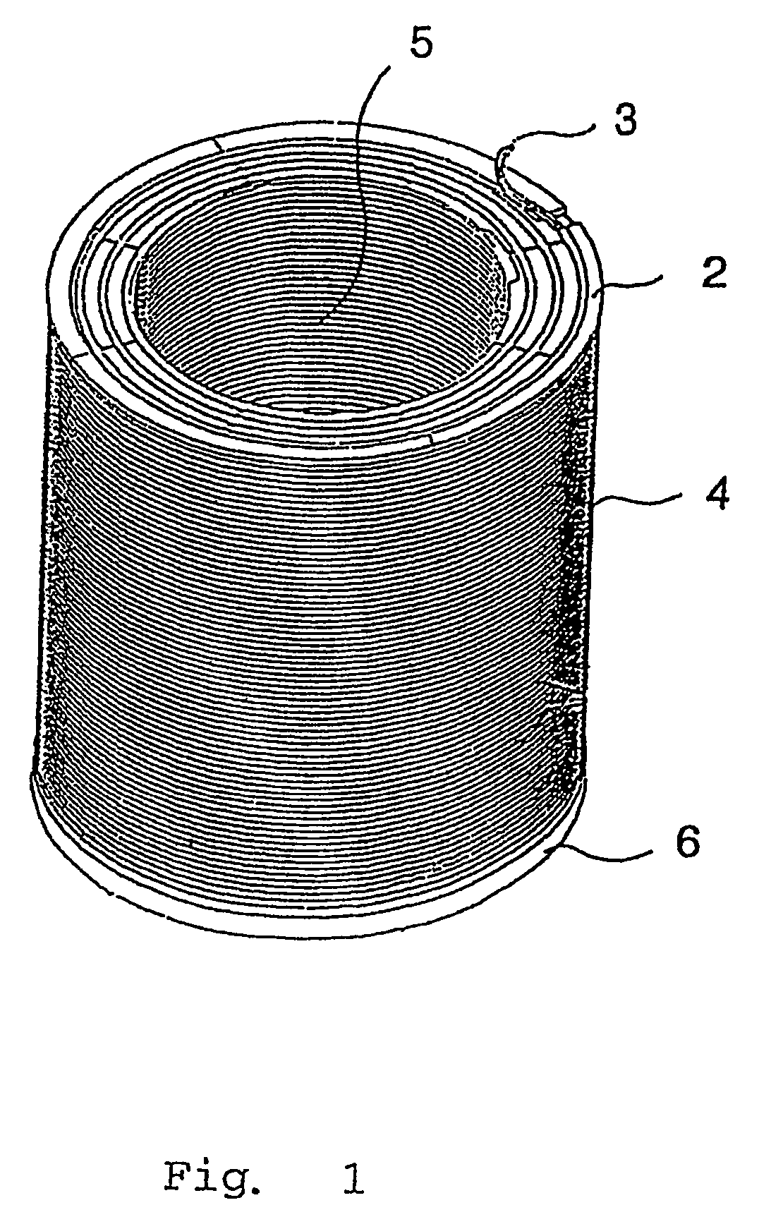
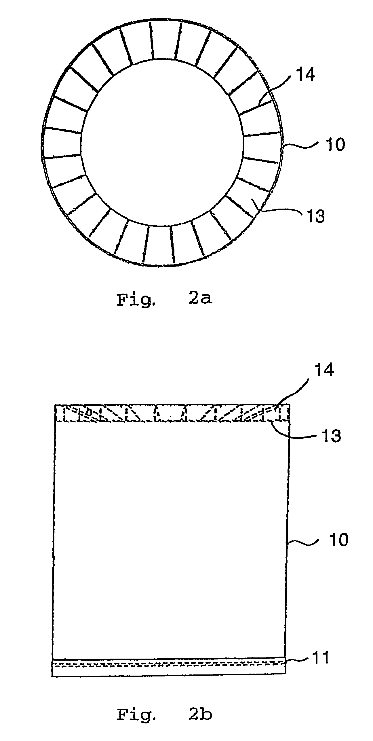
[0013]FIG. 1 shows parts of a cable-wound inductor in the form of a single-phase reactor. The reactor is intended for connection in series with a line in an electric power system (not shown) to limit the magnitude of fault currents. The reactor comprises a supporting structure 2 supporting a cable 3 that is wound so as to form a cylinder-shaped cable winding 4, which surrounds an air-filled centre portion 5 forming the air core of the reactor. The cable 3 is adapted to carry an electric current to generate a magnetic flux in the air core 5. The winding 4 is wound on top of a lower winding plate 6 of glass fibre-reinforced epoxy. On the lower winding plate there is a crescent-shaped slot (not shown) arranged around the envelope surface of the lower winding plate. In addition, four axially directed crescent-shaped slots (not shown) are arranged on the lower winding plate. FIG. 2 shows a fixing member 10 of glass fibre-reinforced epoxy, which is intended to be mounted around the windin...


PUM

PropertyMeasurementUnit
short-circuit forcesaaaaaaaaaa
diameteraaaaaaaaaa
voltagesaaaaaaaaaa

Abstract

A device for absorbing axial and radial short-circuit forces in a cable-wound inductor. A fixing member includes an inner envelope surface that surrounds the cable winding of the inductor.

Description

TECHNICAL FIELD[0001]The present invention relates to a device for absorbing short-circuit forces in an inductor comprising at least one cable winding. In this context, cable winding means a winding constituted by a cable, in which the cable consists of an electric conductor that is surrounded by a solid, continuous insulating material.BACKGROUND ART[0002]Using inductors in electric power systems for transmission of electrical energy is known. Electric power systems in this connection mean systems for voltages exceeding 1 kilo-volt and inductors mean stationary induction machines such as reactors and transformers.[0003]When an inductor is short-circuited, the cable winding of the inductor is subjected to axial and radial short-circuit forces. The radial forces in the inductor act outwards and bring about tensile stresses on the cable that constitutes the winding in the inductor. The axial forces in the inductor act upwards / downwards and bring about shearing stresses on the cable. Wh...

Claims


Application Information

Patent Timeline
Patent Type & Authority Patents(United States)
IPC IPC(8): H01F27/28H01F27/30H01F37/00
CPCH01F37/005H01F27/303
Inventor GUDMUNDSON, SEBASTIAN
Owner ABB (SCHWEIZ) AG
Why Eureka
Try Eureka