Inbound interference reduction in a broadband powerline system

a broadband powerline and inbound interference technology, applied in the field of data transmission, can solve the problems of low risk of interference from external radiation sources, powerline communication systems limited to relatively low data rates, etc., and achieve the effect of reducing the effects of inbound interferen

Active Publication Date: 2006-08-15
AMERICAN TELEPHONE & TELEGRAPH CO
View PDF68 Cites 31 Cited by
  • Summary
  • Abstract
  • Description
  • Claims
  • Application Information

AI Technical Summary

Benefits of technology

[0007]I have recognized that a power line acts as an antenna and may be modeled using antenna analysis techniques. This recogn

Problems solved by technology

Initially, powerline communication systems were limited to relatively low data rates, typically less than 500 kbs.
While existing powerline systems are capable of transmitting data at the rates described above, they were not initially designed for data transmission.
In these low data rate systems, the risk of interference from external radiation sources is low.
The high data rates of BPL systems cannot

Method used


Image

  • Inbound interference reduction in a broadband powerline system
  • Inbound interference reduction in a broadband powerline system
  • Inbound interference reduction in a broadband powerline system

Examples


Embodiment Construction

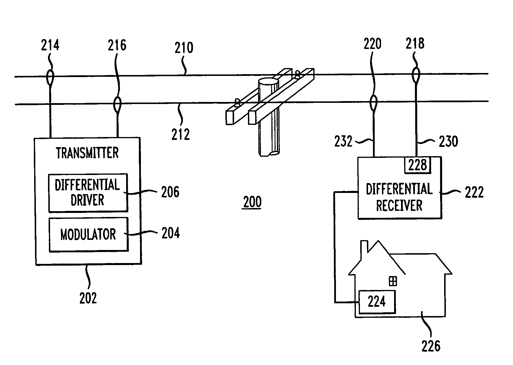
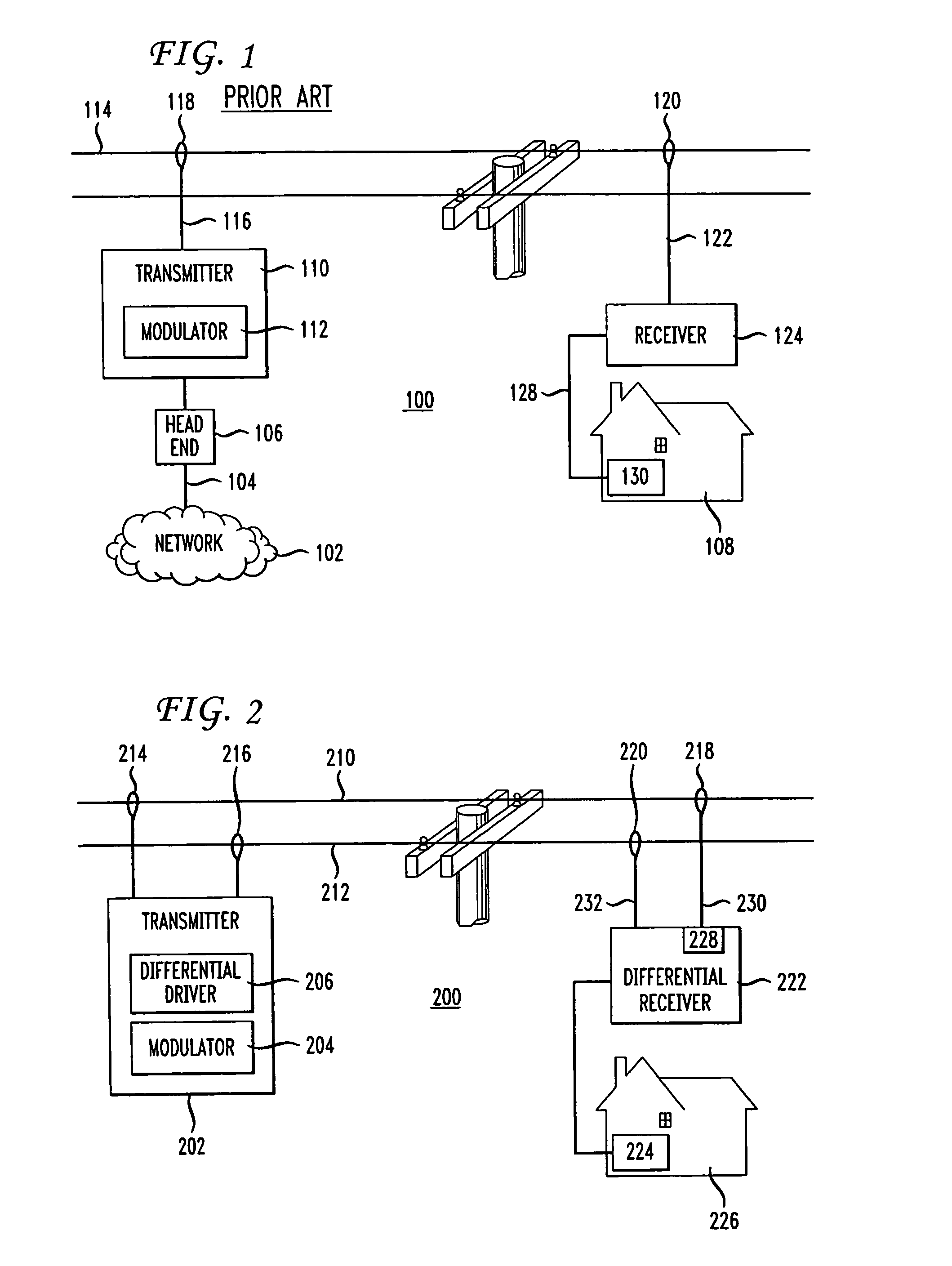
[0014]A typical prior art powerline communication system 100 is shown in FIG. 1. A head end network node 106 is connected to a data network 102 via a fiber optic cable 104. In accordance with a typical network service, the head end 106 is configured to transmit data to end user premises (e.g., premises 108) using powerline cables as the transmission medium. The head end 106 is also configured to convert signals in the optical domain received from fiber 104 to the electrical domain using well known optical to electrical conversion techniques. The head end 106 is connected to a transmitter 110. The transmitter 110 contains a modulator 112 which modulates the data received from head end 106 onto a carrier signal using well known RF modulation techniques. As described above, typical carrier frequencies for a powerline communication system are in the range of 2–30 MHz. The modulated signal is provided to the powerline cable 114 via line 116 and coupler 118. A powerline communication syst...


PUM


Abstract

Disclosed is a method and apparatus for reducing inbound interference in a broadband powerline communication system. Data modulated on first and second carrier frequencies is received via respective first and second lines of the powerline system. A characteristic of at least one of the carrier signals (e.g., phase or amplitude) is adjusted at the receiver in order to reduce the effects of inbound interference on the transmission system. The adjustment parameters may be determined by adjusting the parameters, during a period of no data transmission, until the output of a differential receiver is zero.

Description

CROSS REFERENCE TO RELATED APPLICATIONS[0001]This application is related to commonly assigned patent application Ser. No. 10 / 839,945 filed concurrently herewith on May 6, 2004, entitled Outbound Interference Reduction in a Broadband Powerline System, which is incorporated herein by reference.BACKGROUND OF THE INVENTION[0002]This application relates generally to data transmission, and more particularly to data transmission over power lines.[0003]The use of power lines to transmit data is known. Initially, powerline communication systems were limited to relatively low data rates, typically less than 500 kbs. These low data rates are generally useful for applications such as remote control of various switches connected to the powerline system. More recently, developments have been made in the area of broadband powerline communication systems, also known as powerline telecommunications (PLT) systems or broadband powerline (BPL) systems. These systems are capable of transmitting data at ...

Claims


Application Information

Patent Timeline
IPC IPC(8): G08B1/08
CPCH04B3/54H04B3/56H04L25/10H04B3/30H04B3/542H04J1/08H04L25/028H04B2203/5416H04B2203/5425H04B2203/5483H04L5/0005
Inventor HENRY, PAUL SHALA
Owner AMERICAN TELEPHONE & TELEGRAPH CO
Why Eureka
Try Eureka