
Magnetic recording and reproducing apparatus and method and thin film magnetic head used therein

a technology which is applied in the field of magnetic recording and reproducing apparatus, can solve the problems of difficult to achieve satisfactory contact between each of the elements and a tape, and achieve the effect of improving the transfer rate and preventing the formation of high-precision write track widths

Inactive Publication Date: 2006-08-15
HITACHI LTD
View PDF9 Cites 5 Cited by
  • Summary
  • Abstract
  • Description
  • Claims
  • Application Information

AI Technical Summary

Benefits of technology

[0006]In the technique disclosed in the above-mentioned publication, repetition interval of the head elements is substantially proportional to the number of head elements. If the number of head elements arranged in one head is increased in order to improve a transfer rate, the interval is increased to make it difficult to achieve a satisfactory contact between each of the elements and a tape. Also, since adjacent write tracks are not formed by one scanning, a plurality of times of scannings (drum rotations) are required for forming a pattern of consecutive write tracks. Therefore, high precision formation of the write track widths may be prevented due to factors such as variations among tape tensions and tape feed rates in the scannings.
[0007]An object of the present invention is to provide a magnetic recording and reproducing apparatus, a magnetic recording and reproducing method, and a thin film magnetic head capable of realizing high density and high transfer rate recording by eliminating factors for error in effective track pitch, and readily achieving good contact between each of elements and a recording medium with a reduced track pitch even if the number of head channels is increased.
[0009]As used herein, the write elements of the multitrack write head and the read elements of the multitrack read head have an identical azimuth angle; a read width of the read elements of the multitrack read head is set to substantially ½ of a signal track width formed on the magnetic tape; and repetition interval of the read elements in the track width direction is set to ½ of a signal track pitch, thereby enabling the multitrack read head to read the signals from the group of signal tracks in accordance with a non-tracking system.

Problems solved by technology

If the number of head elements arranged in one head is increased in order to improve a transfer rate, the interval is increased to make it difficult to achieve a satisfactory contact between each of the elements and a tape.

Method used


Image

  • Magnetic recording and reproducing apparatus and method and thin film magnetic head used therein
  • Magnetic recording and reproducing apparatus and method and thin film magnetic head used therein
  • Magnetic recording and reproducing apparatus and method and thin film magnetic head used therein

Examples


Embodiment Construction

[0033]One embodiment of a magnetic recording and reproducing apparatus according to the present invention will hereinafter be described with reference to the drawings.

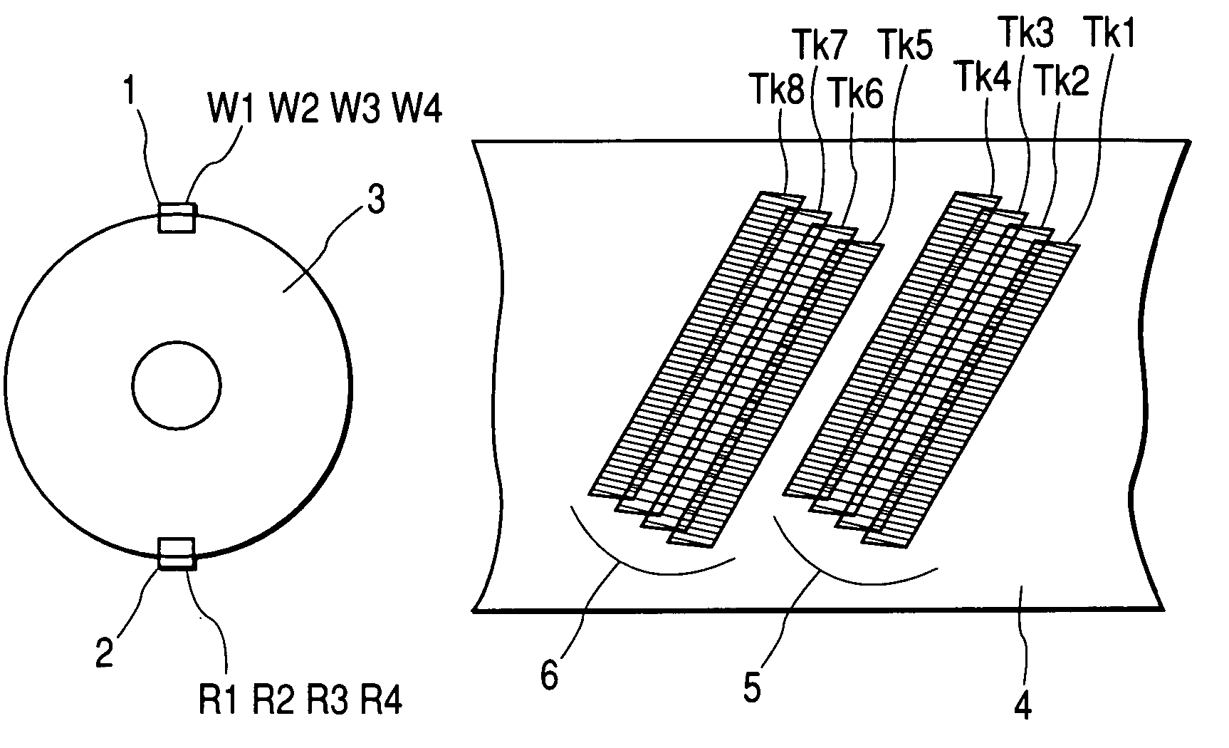
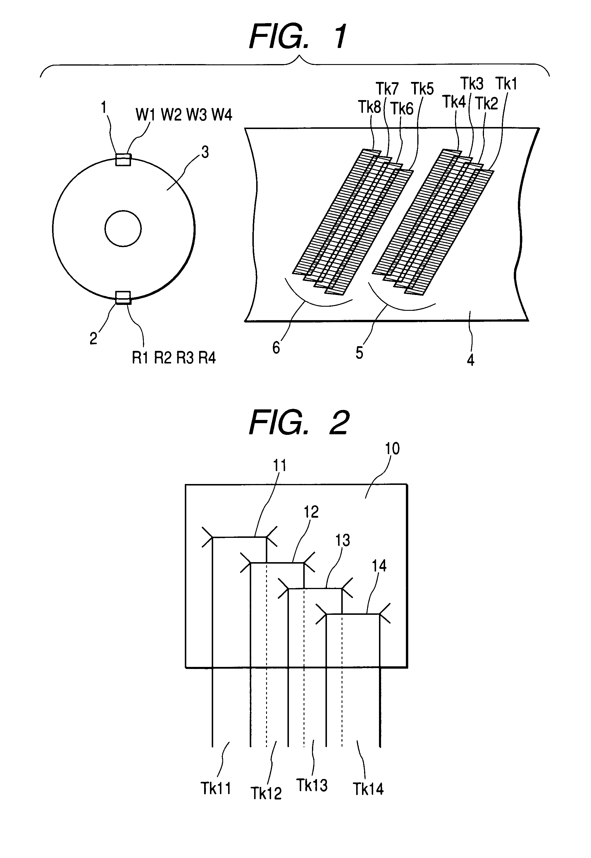
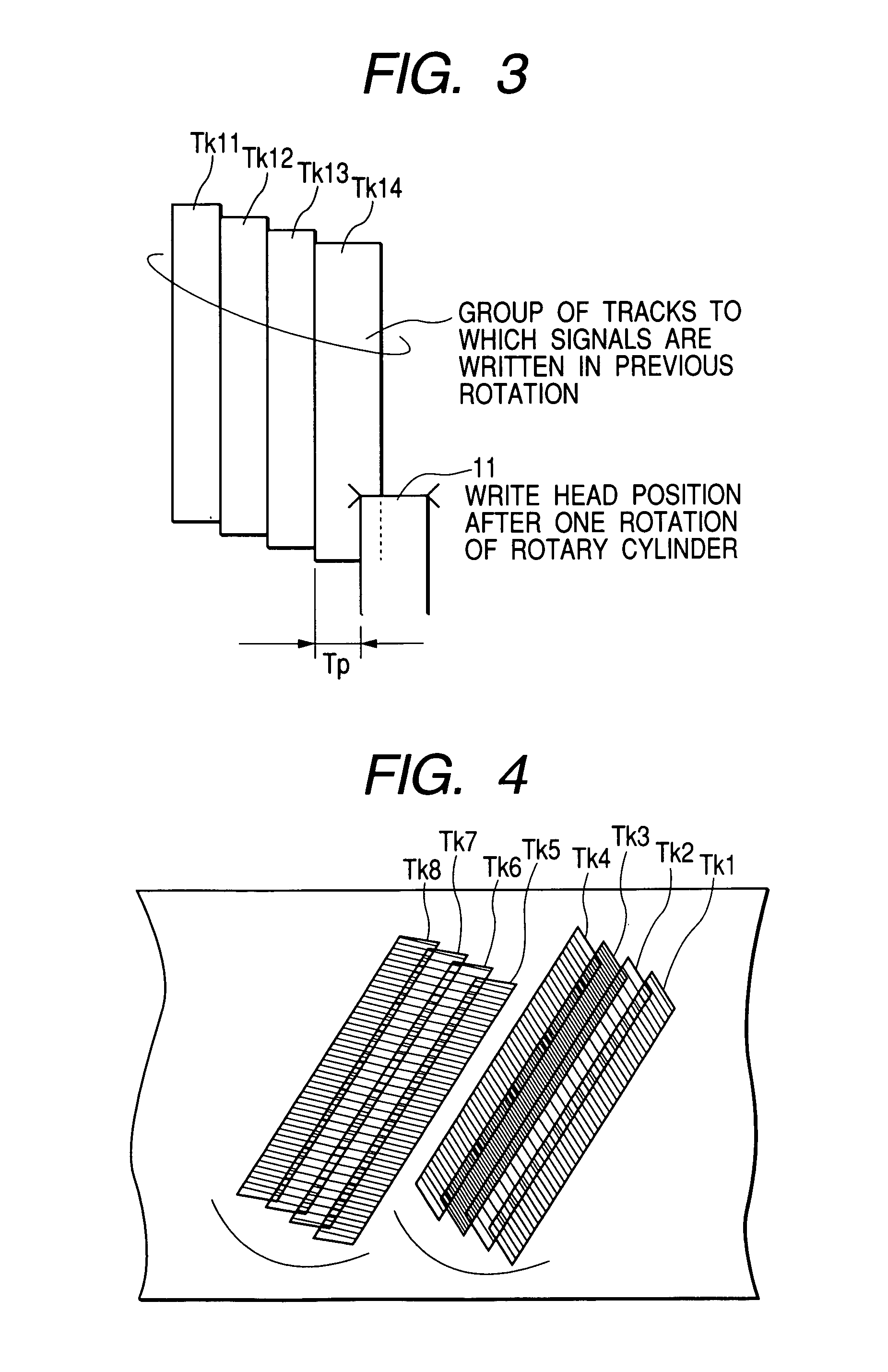
[0034]FIG. 1 is a conceptual diagram for illustrating write tracks in the magnetic recording and reproducing apparatus of the present invention. A multitrack write head 1 having a plurality of tracks (write elements W1, W2, W3, W4) and a multitrack read head 2 having a plurality of tracks (read elements R1, R2, R3, R4) are mounted on a rotary drum 3 as opposed to each other by 180 degrees. A group of write tracks 5 (Tk1, Tk2, Tk3, Tk4) of an identical azimuth are formed on a magnetic tape 4 during one rotation of the rotary drum 3, and a group of tracks (Tk5, Tk6, Tk7, Tk8) are formed on the magnetic tape 4 during a subsequent rotation of the rotary drum 3.

[0035]Referring to FIG. 2, more detailed description of a relationship between the write head 1 and a pattern of the write tracks 5 and 6 shown in FIG. 1 will herein...


PUM


Abstract

The present invention provides a magnetic recording and reproducing apparatus, a magnetic recording and reproducing method, and a thin film magnetic head that enable a good contact between elements and a recording medium with a reduced track pitch even if the number of head channels is increased, thereby realizing high recording density and high transfer rate.At least one multitrack write head having N (N is an integer of 2 or more) write elements arranged along a track width direction in an integral fashion and at least one multitrack read head having L (L is an integer equal to or more than N) read elements arranged along the track width direction in an integral fashion are formed on the rotary drum. The multitrack write head writes signals to a group of N tracks aligned parallel on the magnetic tape during one rotation of the rotary drum, and the multitrack read head reads the group of N signal tracks by the use of any one of the L read elements.

Description

BACKGROUND OF THE INVENTION[0001]1. Field of the Invention[0002]The present invention relates to a magnetic recording and reproducing apparatus and a magnetic recording and reproducing method of the helical scan system to be used for writing and reading signals to and from a magnetic tape, and particularly to a thin film magnetic head having a multitrack structure for high density recording.[0003]2. Description of the Related Art[0004]High density recording in a magnetic recording apparatus using a magnetic tape has been achieved by narrowing a track width and increasing the number of channels. Positions of track ends of write heads arranged on a rotary drum are adjusted so that a width of each of write tracks formed on a recording medium is set to a predetermined value. However, it is difficult to precisely set the write track widths due to influences of precision in mounting height of the write heads, run-out of the rotary drum, wow flutter, and the like.[0005]In view of the above...

Claims


Application Information

Patent Timeline
IPC IPC(8): G11B15/14G11B5/008G11B5/02G11B5/31G11B5/39G11B5/48G11B5/49G11B5/53G11B15/12G11B15/467
CPCG11B5/0086G11B5/00865G11B5/00878G11B5/3106G11B5/3903G11B5/3948G11B15/467G11B5/3967G11B5/4893G11B5/534G11B15/125G11B5/3951G11B5/4976
Inventor TSUCHIYA, TOSHIOINADA, KENKICHIOBATA, AKIHISA
Owner HITACHI LTD
Learn More