Vibration isolating disk drive receiving stations and chassis used in the manufacture and/or testing of hard disk drives

Active Publication Date: 2006-08-15
WESTERN DIGITAL TECH INC
View PDF15 Cites 128 Cited by
  • Summary
  • Abstract
  • Description
  • Claims
  • Application Information

AI Technical Summary

Benefits of technology

[0012]The vibration isolating mass may be greater than the aggregate mass of the nest, the printed circuit board and the disk drive, for example. The nest may have a first surface and a second surface that faces the base, and the vibration isolating mass may be attached to the second surface of the nest. The vibration isolating mass may include cast iron, for example. Other dense materials may also be used. For example, the amount of the vibration isolating mass may be selected to have a weight between 1 and 20 lbs. The vibration isolating mass may define a flat surface, and the nest may include injection molded plastic. The nest may be attached to the flat surface of the vibration isolating mass so as to increase the rigidity and reduce warping of the nest.
[0013]According to another embodiment thereof, the present invention is a disk drive receiving station for carrying out testing and/or servo writing operations on a disk drive. The disk drive receiving station may include a base, a nest assembly and a plurality of elastomeric mounts elastically coupling the nest assembly to the base so as to enable movement of the nest assembly relative to the base. The nest assembly may include a nest tha

Problems solved by technology

As servo track writing is a time consuming process that is directly proportional to the areal density of the disk, reducing the number of servo sectors the servo track writer lays down on the disk saves manufacturing time and costs.
For example, as the number of Tracks per Inch (TPI) of modern drives continues to increase, the driv

Method used


Image

  • Vibration isolating disk drive receiving stations and chassis used in the manufacture and/or testing of hard disk drives
  • Vibration isolating disk drive receiving stations and chassis used in the manufacture and/or testing of hard disk drives
  • Vibration isolating disk drive receiving stations and chassis used in the manufacture and/or testing of hard disk drives

Examples


Embodiment Construction

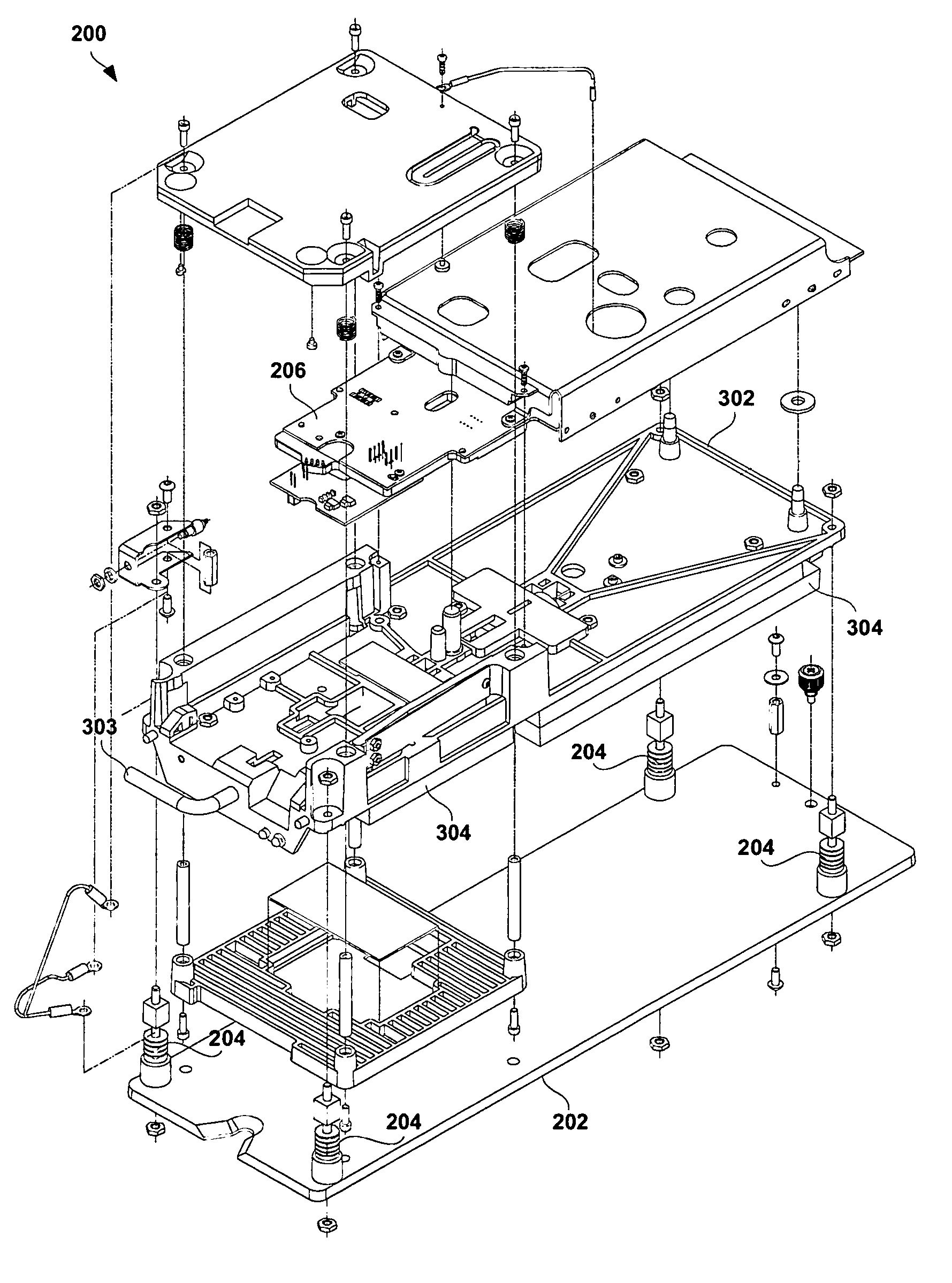
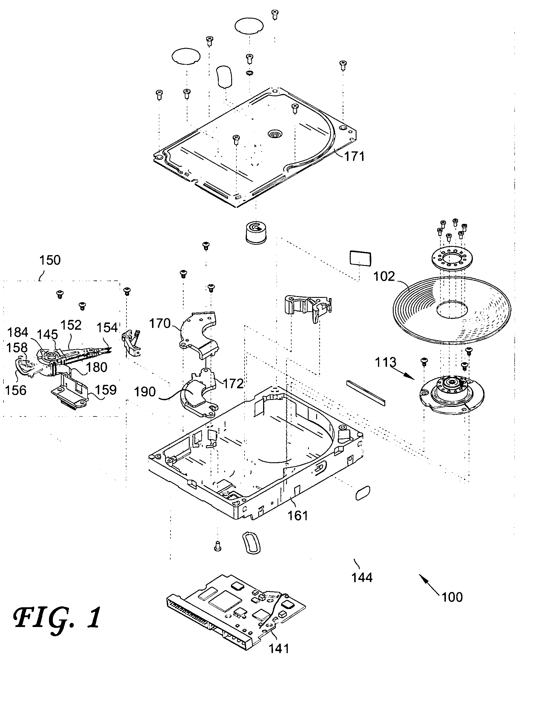
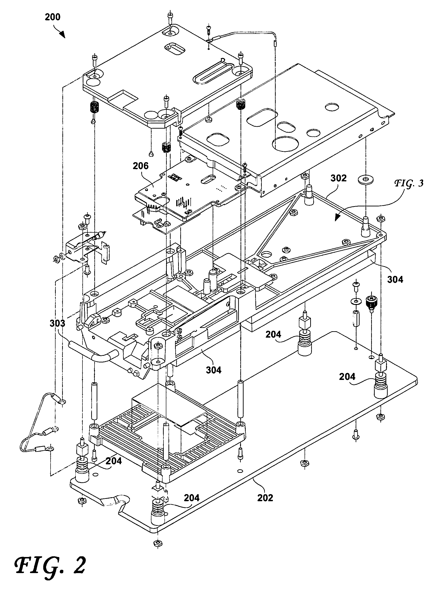
[0019]FIG. 2 is an exploded view that shows a single disk drive receiving station 200, according to an embodiment of the present invention. FIG. 3 is an exploded view that shows further elements of the single disk drive receiving station of FIG. 2. The disk drive receiving station 200 is configured to receive a single disk drive (such as shown in FIG. 1, for example) and to carry out testing and / or servo writing operations on the received disk drive. Considering now FIGS. 2 and 3 collectively, the depicted disk drive receiving station 200 may include a base 202 and a nest assembly. The nest assembly may include a nest 302 and a printed circuit board 206. The nest assembly may be elastically coupled to the base 202 via a plurality of elastomeric mounts 204. The elastomeric mounts 204 enable movement of the nest assembly relative to the base 202. For example, the elastomeric mounts 204 may include rubber mounts or other viscoelastic elements that serve to dampen or dissipate energy fr...


PUM


Abstract

A chassis for receiving a plurality of disk drives includes a plurality of disk drive receiving stations. Each station is configured to carry out testing and/or servo writing operations on a received disk drive. Each station includes a base, a nest assembly and a plurality of elastomeric mounts that elastically couple the nest assembly to the base to enable movement of the nest assembly relative to the base. The nest assembly includes a nest configured to receive and mate with the disk drive and a printed circuit board. Each station includes a separate vibration isolating mass that is coupled to the nest. The vibration isolating mass at least partially isolates vibrations originating within the nest from being transmitted through the elastomeric mounts to other nests in the chassis and at least partially isolates vibrations originating outside the nest from being transmitted through the elastomeric mounts to the nest assembly.

Description

BACKGROUND OF THE INVENTION[0001]1. Field of the Invention[0002]The present invention relates to disk drives. More particularly, the present invention relates to vibration isolating disk drive receiving stations and chassis used in the manufacture and / or testing of disk drives.[0003]2. Description of the Prior Art[0004]FIG. 1 shows the principal components of a magnetic disk drive 100 with which embodiments of the present invention may be practiced. The disk drive 100 comprises a head disk assembly (HDA) 144 and a printed circuit board assembly (PCBA) 141. The elements shown and described in FIG. 1 may be at least partially incorporated within the PCBA 141. The HDA 144 includes a base 161 and a cover 171 attached to the base 161 that collectively house one or more disks 200 (only one disk 102 is shown in FIG. 1), a spindle motor 113 attached to the base 161 for rotating the disk 102, a head stack assembly (HSA) 150, and a pivot bearing cartridge 184 that rotatably supports the HSA 1...

Claims


Application Information

Patent Timeline
IPC IPC(8): H05K5/00F16M11/00F16M13/00G11B33/02
CPCG11B25/043G11B33/08G11B33/00
Inventor HENRY, PAUL H.
Owner WESTERN DIGITAL TECH INC
Why Eureka
Try Eureka