Three-dimensional information acquisition apparatus and three-dimensional information acquisition method

a technology of three-dimensional information and acquisition apparatus, which is applied in the field of three-dimensional information acquisition apparatus and three-dimensional information acquisition method, can solve the problems of difficult image feature correspondence, measurement time and accuracy, and the inability to obtain the shape of an object without textur

Inactive Publication Date: 2006-08-15
OLYMPUS CORP
View PDF28 Cites 68 Cited by
  • Summary
  • Abstract
  • Description
  • Claims
  • Application Information

AI Technical Summary

Benefits of technology

[0029]In view of the above-described drawbacks, it is an object of the present invention to provide a three-dimensional information acquisition apparatus which enables correct decoding from a projection image of a coded pattern with respect to an object having high-saturation colors as well as that having white or low-saturation colors, a projection pattern in three-dimensional information acquisition, and a three-dimensional information acquisition method.
[0051]obtaining a second image by shooting the shooting object without performing illumination using the light from the light source by one of turning off the light source and preventing transmission of the light from the light source;

Problems solved by technology

Under the present situation, however, there is a problem in measurement time and accuracy, and the latter triangulation method is mainly used.
This method has drawbacks that the correspondence of features in the images is difficult and the shape of an object having no texture cannot be obtained.
As the former pattern form coding, one based on distribution of an opening width of the slit and that based on utilization of an M sequence code are proposed, but they have a problem in measurement density and measurement stability.
It is said that they serve no practical use.
In the time-series coding using the binary pattern, however, sufficient measurement cannot be taken when the camera is not fixed on a tripod but held in the hand or when an object such as a human being or an animal cannot stay still.
That is because the shooting cannot be finished within a time which can allow a camera shake or blurring of an object if a number of times of projection is large.
Further, there is also a restriction in flash charging time or the quantity of light emission, and the number of times of projection which can satisfy such a restriction is not enough.
Therefore, when there is non-linearity such as a gamma characteristic in an acquired image, a decoding error is apt to occur in an area where a difference in reflection brightness is small, and stable measurement under regular illumination is difficult.
In order to solve these problems, reference projection or the like is proposed in the above cited reference, but this is not realistic because the number of times of projection is increased.
As described above, coding using the multi-gradation of brightness is easily affected by fluctuations in brightness, and hence setting an appropriate threshold value is difficult.
In the prior art color pattern projection method using colors, however, it is difficult to measure a three-dimensional shape of an object which has a high-saturation color in particular.
That is, decoding is difficult with respect to an object having such a surface reflectivity characteristic as that even one of R, G and B components has a reflection signal which is close to zero.
In other words, decoding can be successfully performed with respect to a surface of an object which has a white color or a low-saturation color, but judgment based on colors obtained from combinations of R, G and B becomes difficult with respect to an object having such a surface reflectivity characteristic as that even one of reflection signals of the R, G and B components has a value on the noise level close to zero.

Method used


Image

  • Three-dimensional information acquisition apparatus and three-dimensional information acquisition method
  • Three-dimensional information acquisition apparatus and three-dimensional information acquisition method
  • Three-dimensional information acquisition apparatus and three-dimensional information acquisition method

Examples


first embodiment

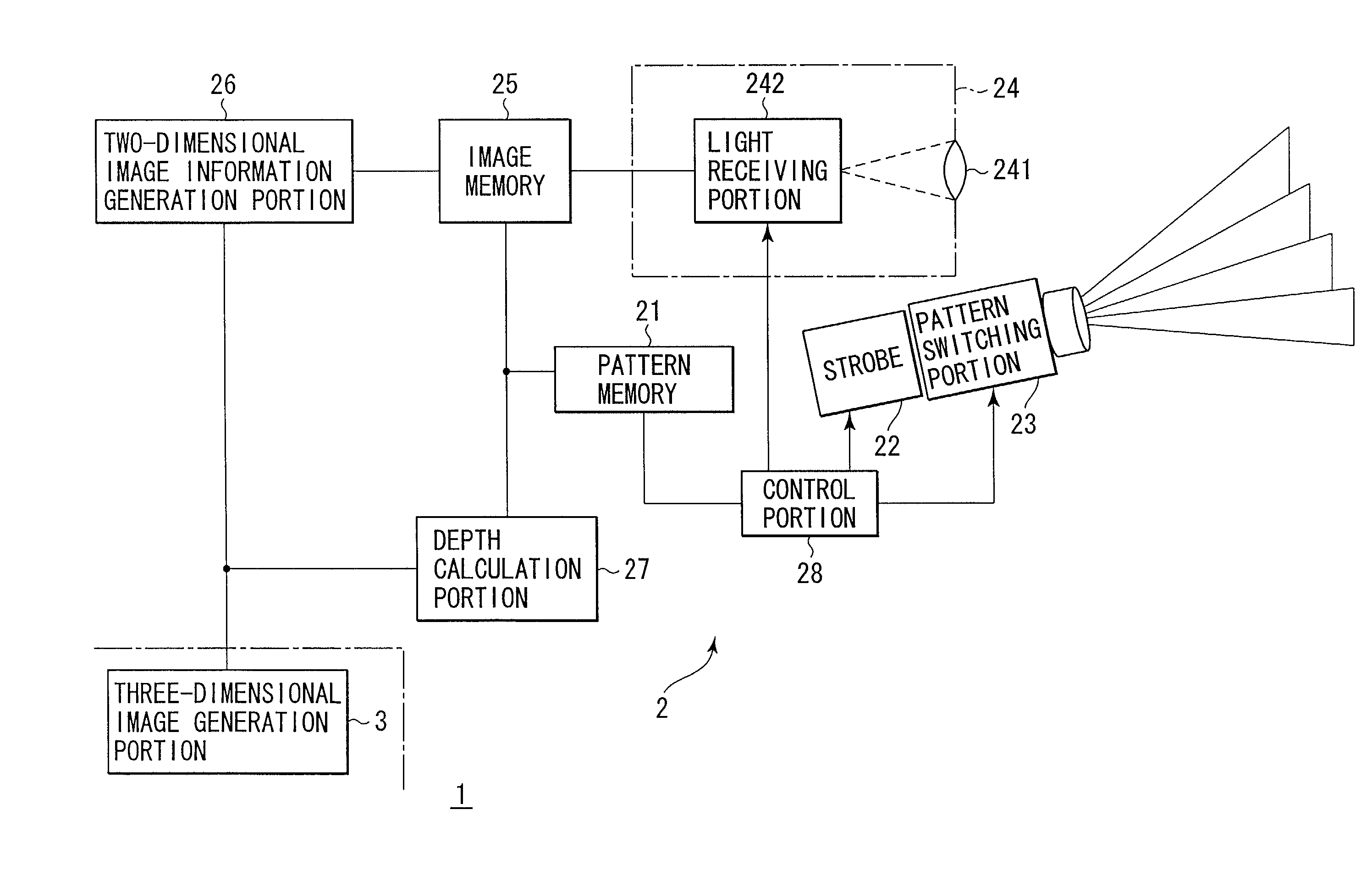
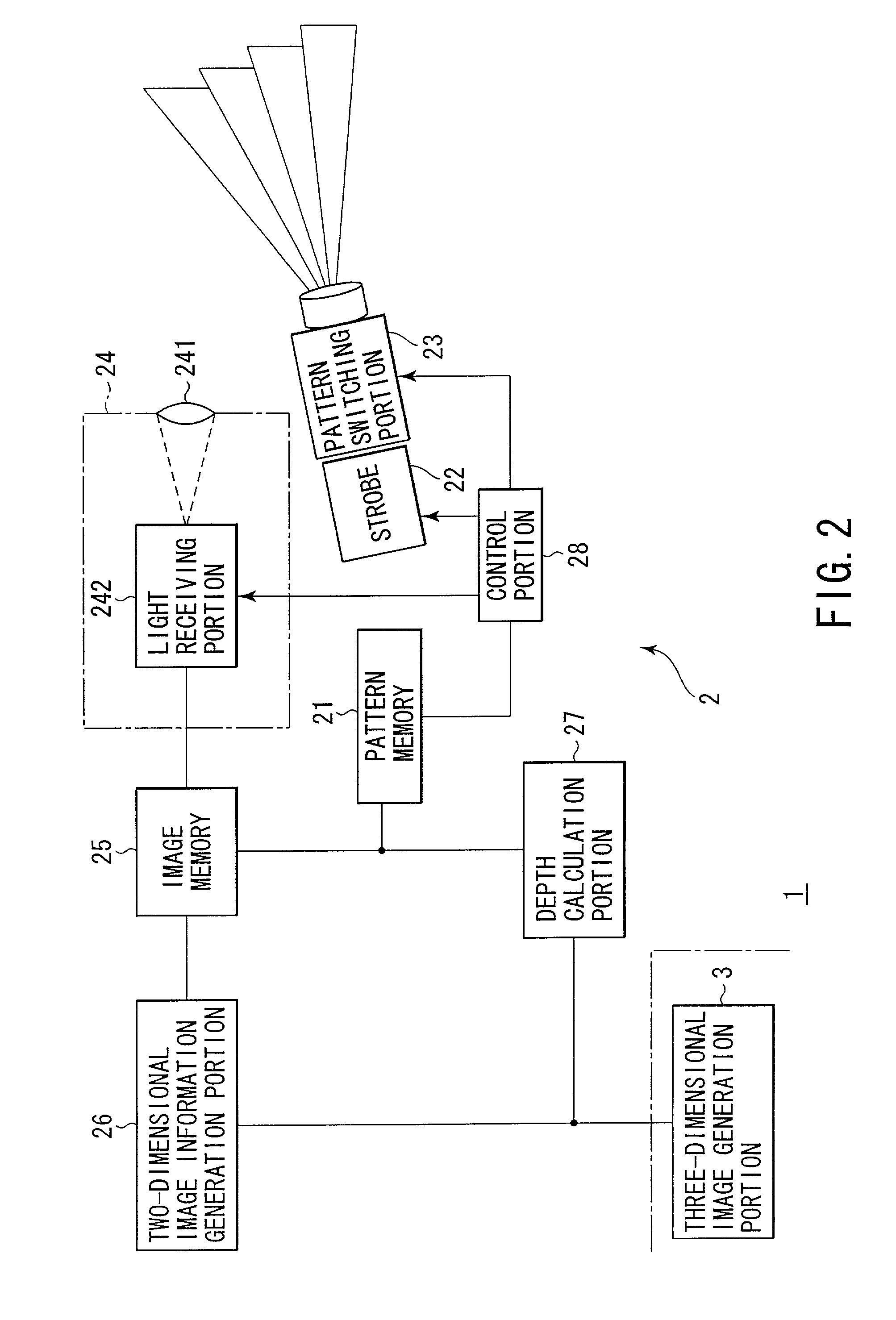
[0079]FIG. 2 is a view showing a structure of a three-dimensional shape measurement apparatus 1 to which a three-dimensional information acquisition apparatus according to a first embodiment of the present invention is applied.

[0080]This three-dimensional shape measurement apparatus 1 is constituted by a three-dimensional information acquisition apparatus 2 according to a first embodiment of the present invention and a three-dimensional image generation portion 3. The three-dimensional information acquisition apparatus 2 is configured by a pattern memory 21, a strobe 22, a pattern switching portion 23, a shooting portion 24, an image memory 25, a two-dimensional image information generation portion 26, a depth calculation portion 27 and a control portion 28.

[0081]Here, the pattern memory 21 stores therein a code sequence or the like of a projection pattern to be projected onto an object (not shown). The strobe 22 is used for emitting the light, and the pattern switching portion 23 s...

second embodiment

[0125]The second embodiment according to the present invention will now be described. In this second embodiment, the method part is the same as the three-dimensional information acquisition method used in the first embodiment, but the apparatus structure is different.

[0126]That is, as shown in FIG. 6, a three-dimensional information acquisition apparatus 2 according to the second embodiment is constituted by a pattern memory 21 which stores therein a pattern to be projected onto an object, a strobe 22 used for emitting light, a pattern switching portion 23 which switches presence / absence of the pattern which modulates the intensity (transmissivity) of the light depending on a position, condenser lenses 241R and 241L which condense the reflected light, light receiving portions 242R and 242L which receives the light condensed by the condenser lenses 241R and 241L, image memories 25R and 25L which store therein a taken image, a two-dimensional image information generation portion 26 wh...

third embodiment

[0135]A third embodiment according to the present invention will now be described.

[0136]The apparatus structure according to the third embodiment is similar to that according to the first embodiment or the second embodiment. A difference lies in that the influence of the external light is suppressed by shooting with a high-speed shutter (for example, 1 / 500 second). As a result, non-flash shooting without a pattern can be eliminated, and fetching the image can be thereby completed by the two times of shooting, i.e., the projection pattern shooting and the flash shooting without a pattern.

[0137]Based on this, the flow of processing becomes slightly simpler than that of the first embodiment or the like. This will now be described with reference to FIG. 7.

[0138]The coded color pattern 4 is first projected onto the object (step S1). Then, the projected pattern is shot with the high-speed shutter, and the obtained image data (Pr, Pg and Pb) is input to the image memory 25 (step S2).

[0139]...


PUM


Abstract

There are performed three types of object shooting, i.e., a projection pattern shooting using a pattern including both characterization of a stripe based on a color and characterization based on a gradation of the same component, a flash shooting without a pattern and a non-flash shooting without a pattern. A two-dimensional image information generation portion corrects the influence of a surface reflectivity of an object or external light from the three types of images, and estimates a pattern structure using the characteristic based on a color with respect to an object having a white-based color or a low-saturation color and based on a gradation with respect to an object having a high-saturation color. A depth calculation portion specifies the correspondence relationship between the estimated pattern structure and information of the projected pattern, and calculates a depth of each part of the object based on a result of specification.

Description

CROSS-REFERENCE TO RELATED APPLICATIONS[0001]This application is based upon and claims the benefit of priority from the prior Japanese Patent Applications No. 2001-193555, filed Jun. 26, 2001; and No. 2002-128905, filed Apr. 30, 2002, the entire contents of both of which are incorporated herein by reference.BACKGROUND OF THE INVENTION[0002]1. Field of the Invention[0003]The present invention relates to a three-dimensional information acquisition apparatus capable of acquiring a depth value by projecting a pattern on a object and obtaining the correspondence between a light receiving pattern and a light projection pattern in order to measure a three-dimensional shape, a projection pattern in such three-dimensional information acquisition, and a three-dimensional information acquisition method.[0004]2. Description of the Related Art[0005]As conventional methods for measuring the shape of a three-dimensional object, there are roughly two types of methods. One is a method based on measu...

Claims


Application Information

Patent Timeline
Patent Type & Authority Patents(United States)
IPC IPC(8): G06K9/00G01B11/25G02B7/28G06T1/00G06T5/00H04N13/239
CPCG01B11/25G02B7/28G06T7/0057H04N5/2226H04N13/0207H04N13/0239H04N13/0253H04N13/0257G06T2207/10012H04N2013/0081H04N13/0055G06T7/521H04N13/254H04N13/189H04N13/207H04N13/257H04N13/239
Inventor SHIRATANI, FUMIYUKI
Owner OLYMPUS CORP
Why Eureka
Try Eureka