Fiber optic cable with composite polymeric/metallic armor

a fiber optic cable and polymer technology, applied in the field of fiber optic communications cables, can solve the problems of difficult bending of cables, heavy mechanical loads, moisture and heat, etc., and achieve the effects of reducing the number of cables, and reducing the service life of cables

Inactive Publication Date: 2006-08-15
COMMSCOPE INC
View PDF11 Cites 20 Cited by
  • Summary
  • Abstract
  • Description
  • Claims
  • Application Information

AI Technical Summary

Benefits of technology

[0006]The present invention is directed to a fiber optic cable that can meet the electrical and performance demands of pavement crossing applications while being more flexible and resistant to kinking than typical cables used in such environments. As a first aspect of the invention, a fiber optic cable comprises: a plurality of optical fibers; a tube circumferentially surrounding the optical fibers, the tube being formed of a first polymeric material; an armor circumferentially surrounding and fixed relative to the tube, the armor being formed of a metallic material; and a jacket circumferentially surrounding the armor, the jacket being formed of a second polymeric material. In this configuration, the cable can provide the requisite mechanical, electrical, handling and connectorizing properties for use in applications such as pavement crossings.

Problems solved by technology

Cables employed in this environment are subjected to potentially heavy mechanical loads, moisture, and heat.
Also, with many cables flexibility facilitates handling and installation of the cable, but the cable should not buckle when bent, as buckling can negatively impact the optical and mechanical properties of the cable.
However, the relatively thick metal tube can also render the cable difficult to bend.

Method used


Image

  • Fiber optic cable with composite polymeric/metallic armor
  • Fiber optic cable with composite polymeric/metallic armor
  • Fiber optic cable with composite polymeric/metallic armor

Examples


Embodiment Construction

[0013]The present invention will now be described more fully hereinafter, in which preferred embodiments of the invention are shown. This invention may, however, be embodied in different forms and should not be construed as limited to the embodiments set forth herein. Rather, these embodiments are provided so that this disclosure will be thorough and complete, and will fully convey the scope of the invention to those skilled in the art. In the drawings, like numbers refer to like elements throughout. Thicknesses and dimensions of some components may be exaggerated for clarity.

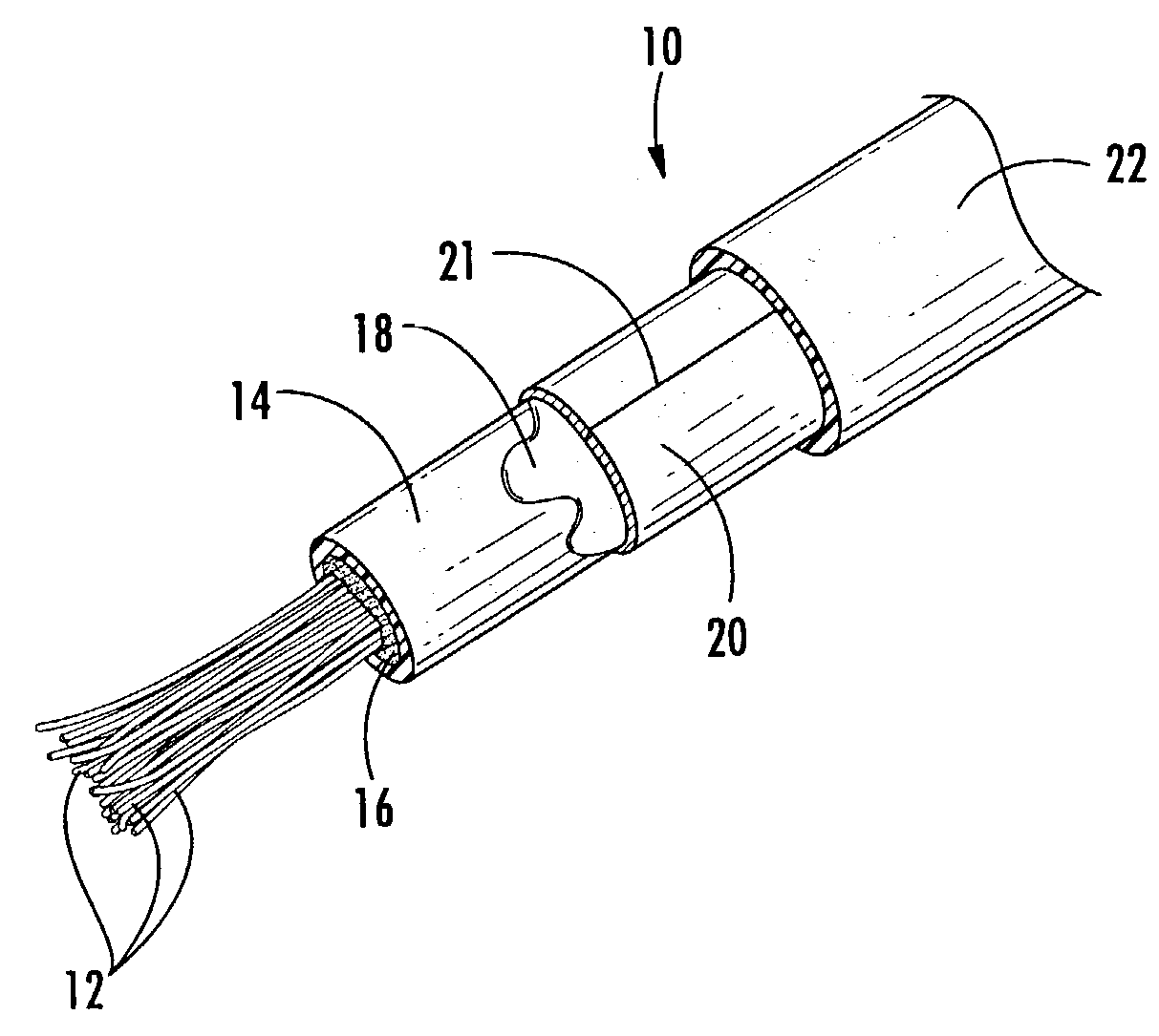
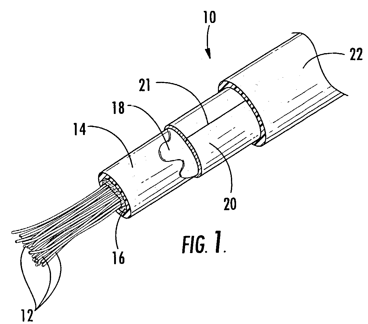
[0014]Referring now to the drawings, a fiber optic cable, designated broadly at 10, is shown in FIG. 1. The cable 10 includes a plurality of optical fibers 12, an elongate polymeric tube 14 that contains the optical fibers 12, a metallic armor 20 that circumferentially surrounds the tube 14, and an outer jacket 22 that circumferentially surrounds the armor 20. These components are discussed in greater detail be...


PUM

PropertyMeasurementUnit
thicknessaaaaaaaaaa
thicknessaaaaaaaaaa
outer diameteraaaaaaaaaa

Abstract

A fiber optic cable includes: a plurality of optical fibers; a tube circumferentially surrounding the optical fibers, the tube being formed of a first polymeric material; an armor circumferentially surrounding and fixed relative to the tube, the armor being formed of a metallic material; and a jacket circumferentially surrounding the armor, the jacket being formed of a second polymeric material. In this configuration, the cable can provide the requisite mechanical, electrical, handling and connectorizing properties for use in applications such as pavement crossings.

Description

FIELD OF THE INVENTION[0001]The present invention relates generally to communications cables, and more specifically to fiber optic communications cables.BACKGROUND OF THE INVENTION[0002]Fiber optic cables include optical fibers which transmit information in cable television, computer, power, and telephone systems. Typically, fiber optic cables include a plurality of optical fibers housed within one or more protective layers. The number of fibers included in the cable, and the materials and thicknesses thereof used to form the protective layers, are selected based on the type of application or installation of the cable.[0003]One specialized cable application is a “pavement crossing,” in which a cable is laid across an existing section of pavement, asphalt, or the like. Conventionally, a slot of about 10 mm is formed in the pavement section. Fiber optic cable is placed in the slot, a bedding material (such as Neoprene rubber) is placed over the cable, and the slot is then patched with...

Claims


Application Information

Patent Timeline
Patent Type & Authority Patents(United States)
IPC IPC(8): G02B6/44G02B6/46G02B6/50H01B11/00H02G1/06
CPCG02B6/4429G02B6/504G02B6/4488
Inventor ADAMS, SCOTT M.PASCHAL, KEVIN S.SHINOSKI, JARRETT S.TRAVIS, TODD R.WANDEL, LEE E.WESSELS, ROBERT A.
Owner COMMSCOPE INC
Why Eureka
Try Eureka